Aplex Technology ACS-2702 User Manual
Page 20
ACS-2702 User Manual 19
27. LED1:
LED STATUS. Green LED for Motherboard Power status.
28. LED2:
LED STATUS. Green LED for Motherboard Standby Power Good status.
29. CN1:
(DF13-40P Connector),For expand output connector, It provides one 18/24bit single
channel LVDS, one Backlight control, two USB ports, one power led, one HDD LED,
one power on/off button, one RESET.
Function
Signal Name
Pin#
Signal Name
Function
LVDS
12V_S0
2
1
12V_S0
LVDS
BKLT_EN_OUT
4
3
BKLT_CTRL
Ground
6
5
Ground
LVDS_VDD5
8
7
LVDS_VDD5
LVDS_VDD3
10
9
LVDS_VDD3
Ground
12
11 Ground
LA_DATAP0
14
13 LA_DATAN0
LA_DATAP1
16
15 LA_DATAN1
LA_DATAP2
18
17 LA_DATAN2
LA_DATAP3
20
19 LA_DATAN3
LA_CLKP
22
21 LA_CLKN
Ground
24
23 Ground
Ground
26
25 Ground
USB1
USB1_P
28
27 USB1_N
USB1
USB0
USB0_P
30
29 USB0_N
USB0
5V_USB01
32
31 5V_USB01
USB1
5V_USB01
34
33 5V_USB01
PWR LED
PWR_LED+
36
35 HDD_LED+
HDD LED
Ground
38
37 Ground
PWR ON/OFF PWRBTN_ON-
40
39 FP_RST-
RESET
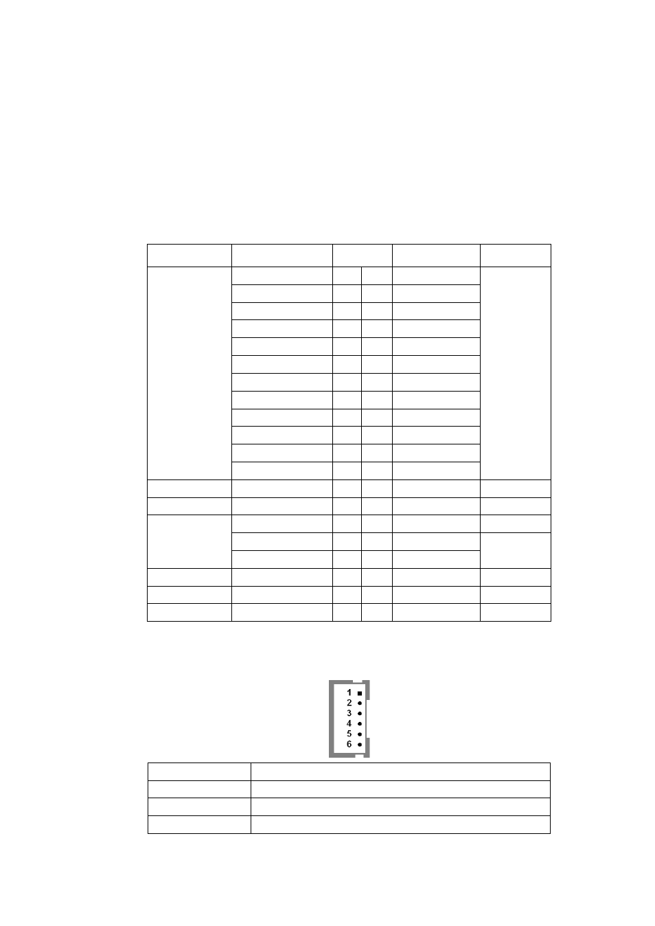
INVT1:
(2.0mm Pitch 1x6 Pin wafer connector), Backlight control connector for LVDS.
Pin#
Signal Name
1
+DC12V
2
+DC12V
3
Ground