Aplex Technology ACS-2702 User Manual
Page 15
ACS-2702 User Manual 14
Pin4-Pin6(Close)
VGA Simulation Disabled
Pin4-Pin6(Open)
VGA Simulation Enabled
use the 2.0mm jumper cap to close pin 4 and pin6
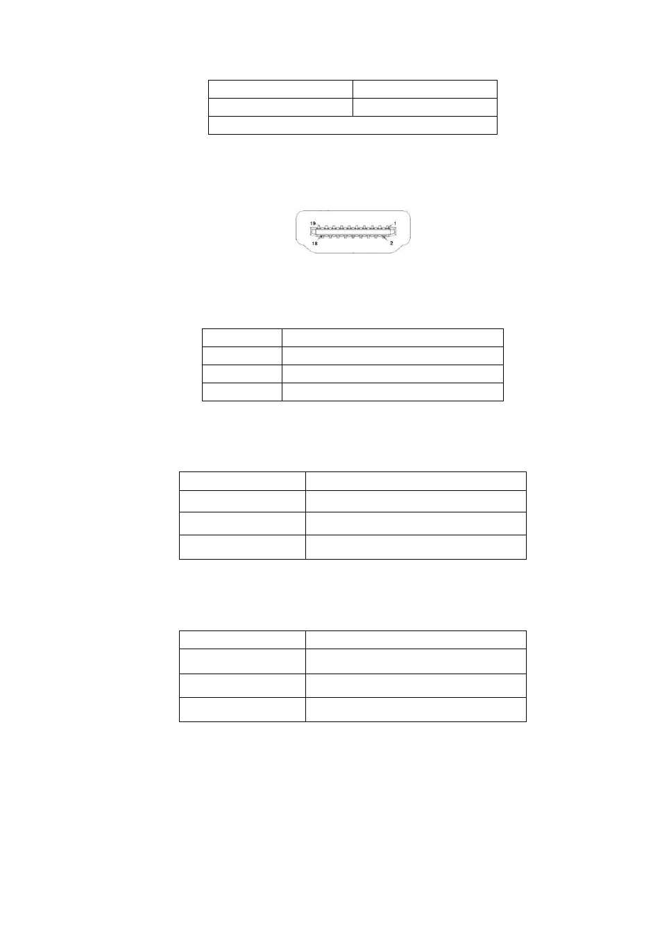
7. HDMI1:
(HDMI 19P Connector), High Definition Multimedia Interface connector.
8. JP1:
(2.0mm Pitch 2x3 Pin Header), COM1 jumper setting, pin 1~6 are used to select signal
out of pin 9 of COM1 port.
JP1 Pin#
Function
Close 1-2
COM1 RI (Ring Indicator) (default)
Close 3-4
COM1 Pin9=+5V
(option)
Close 5-6
COM1 Pin9=+12V
(option)
9. S_232:
(Switch), COM1 jumper setting, it provides selectable RS232 or RS422 or RS485 serial
signal output.
Function
S_232 Pin#
RS232 (Default)
ON: Pin1, Pin2, Pin3, Pin4
RS422 (option)
OFF: Pin1, Pin2, Pin3, Pin4
RS485 (option)
OFF: Pin1, Pin2, Pin3, Pin4
10. S_422:
(Switch), COM1 setting, it provides selectable RS232 or RS422 or RS485 serial signal
output.
Function
S_422 Pin#
RS232 (Default)
OFF: Pin1, Pin2, Pin3, Pin4
RS422 (option)
ON: Pin1, Pin2, Pin3, Pin4
RS485 (option)
ON: Pin1, Pin2, Pin3, Pin4
11. COM1:
(Type DB9),Rear serial port, standard DB9 Male serial port is provided to make a
direct connection to serial devices. COM1 port is controlled by pins No.1~6 of
JP1,select output Signal RI or 5V or 12V, For details, please refer to description of JP1
and S_232 and S_422 setting.