Aplex Technology ACS-2702 User Manual
Page 17
ACS-2702 User Manual 16
8
NC
9
NC
BIOS Setup:
Advanced/W83627UHG Super IO Configuration/Serial Port
1 Configuration【RS-485】
12. JP2:
(2.0mm Pitch 2x3 Pin Header),COM2 jumper setting, pin 1~6 are used to select signal
out of pin 9 of COM2 port.
JP2 Pin#
Function
Close 1-2
COM2 RI (Ring Indicator) (default)
Close 3-4
COM2 Pin9=+5V
(option)
Close 5-6
COM2 Pin9=+12V
(option)
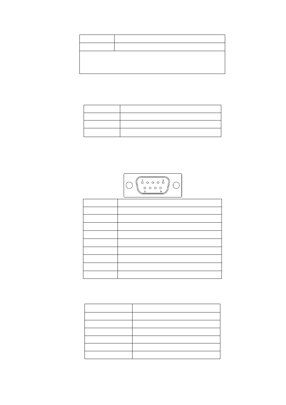
13. COM2:
(Type DB9),Rear serial port, standard DB9 Male serial port is provided to make a
direct connection to serial devices.
Pin#
Signal Name
1
DCD# (Data Carrier Detect)
2
RXD (Received Data)
3
TXD (Transmit Data)
4
DTR (Data Terminal Ready)
5
Ground
6
DSR (Data Set Ready)
7
RTS (Request To Send)
8
CTS (Clear To Send)
9
RI (Ring Indicator)
14. TCH1:
(2.0mm Pitch 1x6 box Pin Header), internal Touch controller connector.
Pin#
Signal Name
1
SENSE
2
X+
3
X-
4
Y+
5
Y-
6
GND_EARCH