Aplex Technology APC-3218 User Manual
Page 23
APC-3X18 User Manual
23
Procedures of CMOS clear:
a) Turn off the system and unplug the power cord from the power outlet.
b) To clear the CMOS settings, use the jumper cap to close pins1 and 2 for about
3 seconds then reinstall the jumper clip back to pins open.
c) Power on the system again.
d) When entering the POST screen, press the key to enter CMOS
Setup Utility to load optimal defaults.
e) After the above operations, save changes and exit BIOS Setup.
3. BAT1 :
(1.25mm Pitch 1X2 box Pin Header) 3.0V Li battery is embedded to provide
power for CMOS.
Pin#
Signal Name
Pin1
VBAT
PIN2
Ground
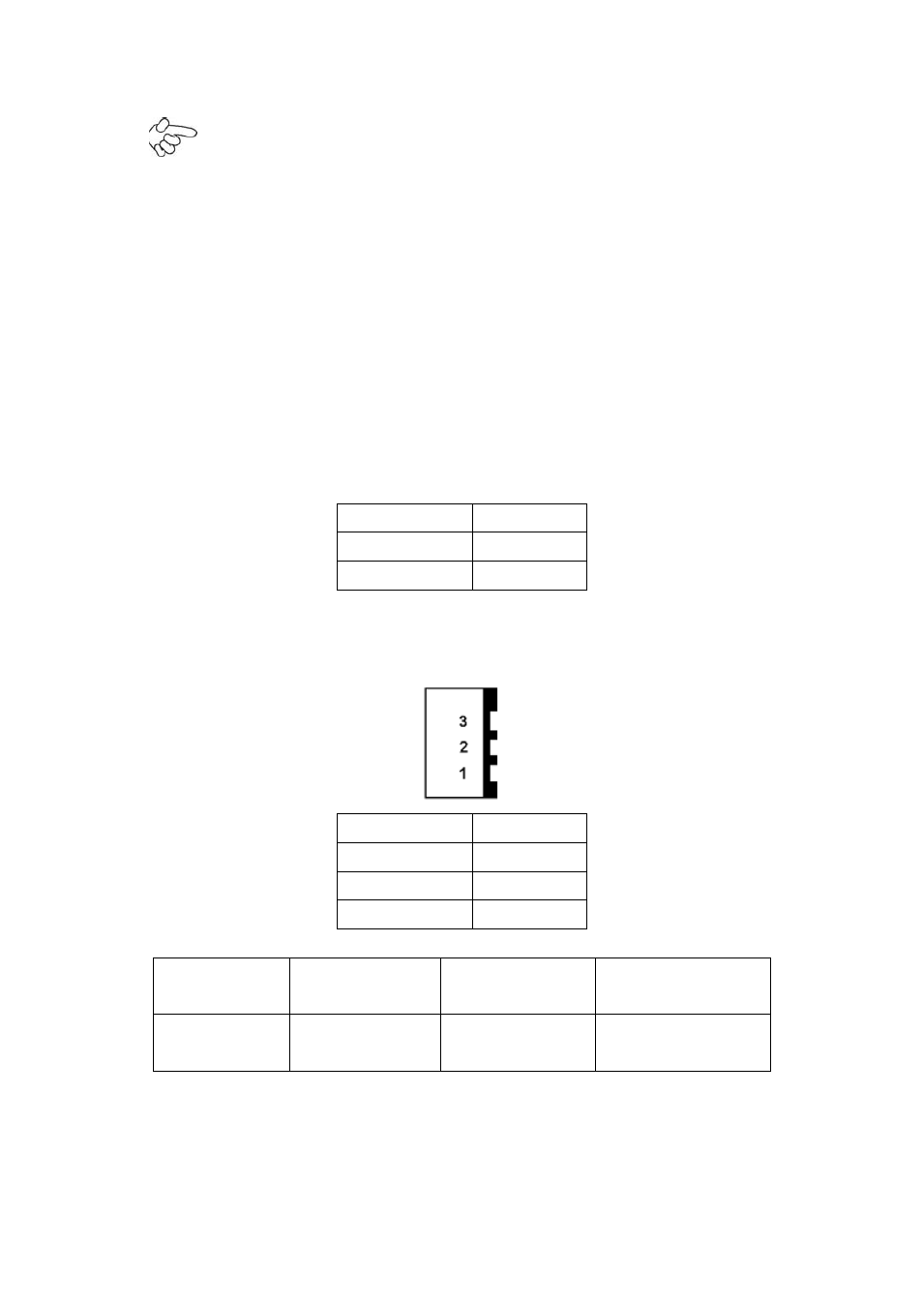
4. DCIN:
(5.08mm Pitch 1x3 Pin Connector),DC9V ~ DC32V System power input connector.
Pin#
Power Input
Pin1
DC+9V~32V
Pin2
Ground
Pin3
PG
Power Mode
Location: DCIN
(5.4.4.)
Location: ATX12V
(5.4.5.)
Location: ATX
(5.4.6.)
AT
(Default)
input
DC9~32V
output
DC 12V
NC
5. ATX12V:
(2x2 Pin Connector),DC12V System power
output
connector.