Wireless digital clock installation, Digital single display flush mounting – American Time Wireless Remote Transmitter User Manual
Page 23
23
© American Time
Wireless Remote Transmitter Installation Manual
Glossary
Appendix
Troubleshooting
Clock
Installation
Transmitter and
System Setup
Intr
oduction
Wireless Digital Clock
Installation
n
Note: Time format (12 or 24 hour) for Wireless Digital Clocks is set in Remote Transmitter Connect. The format can be viewed or changed
in Remote Transmitter Connect under the Configuration Tab, Time Display Format 12 Hour 24 Hour.
CAUTION: RISK OF ELECTRICAL SHOCK - Disconnect and lock out power to the
electrical box before installing or servicing the clock.
u
Remove the hanger from the clock by removing the screw on top of the clock.
v
Mount the hanger on the wall to a single or double gang box.
w
Make electrical connections (black to hot, white to neutral and green to ground)
for the Molex cable (not wired to the clock) to a non-switched electrical circuit
wiring using UL approved wire nuts. Route field wiring away from sharp
projections and corners.
x
Join the wall and clock Molex together.
y
Mount the clock on the hanger and secure with the screw removed in Step 1.
z
Remove plastic protector from display face.
Apply power to the circuit and confirm correct operation.
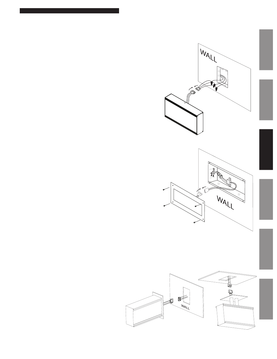
Digital Single Display Surface Mounting
Digital 2-Sided Display - Ceiling or Wall Mount
u
Make electrical connections (black to hot, white to
neutral and green to ground) for the Molex cable (not
wired to the clock) to non-switched electrical circuit
wiring using UL approved wire nuts. Route field wiring
away from sharp projections and corners.
v
Join the wall/ceiling and clock Molex together.
w
Mount the clock to the ceiling (4" box) or wall (single or
double gang box).
x
Remove plastic protector from display face.
y
Apply power to the circuit and confirm correct operation.
Digital Single Display Flush Mounting
CAUTION: RISK OF ELECTRICAL SHOCK - Disconnect and lock out power to the
electrical box before installing or servicing the clock.
u
Remove the four sheet metal screws that hold the cover assembly and
enclosure base together. Be sure to keep the sheet metal screws for
reassembly.
v
Mount the enclosure base into the wall. Opening is 12
1
⁄
2
" x 7
1
⁄
2
" x 3
1
⁄
2
".
w
Run interconnecting field wires through the enclosure base.
x
Make electrical connections (black to hot, white to neutral, green to ground
wires) to non-switched electrical circuit wiring using UL approved wire nuts.
Route field wiring away from sharp projections, corners and internal
components.
y
Join both Molex connectors together, placing excess wiring and Molex
connectors into the box.
z
Re-attach the cover assembly to the enclosure base using the sheet metal
screws removed in Step 1.
Remove plastic protector from display face.
Apply power to the circuit and confirm correct operation.
CEILING
CAUTION: RISK OF ELECTRICAL SHOCK - Disconnect and lock out power to the
electrical box before installing or servicing the clock