Remote transmitter connect web interface – American Time Wireless Remote Transmitter User Manual
Page 17
17
© American Time
Wireless Remote Transmitter Installation Manual
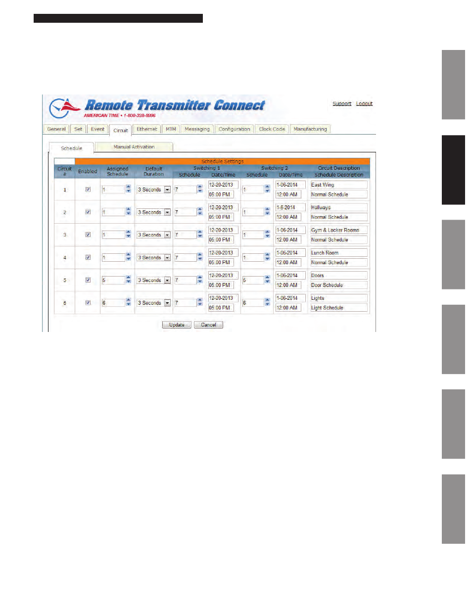
Circuit Tab:
The Circuit Tab contains circuit designations to specific schedules. This tab also contains the Manual Activation feature which allows manual
activation of relays.
Schedule:
Figure 5
1. Enabled: This allows the user to enable or disable the circuit. The circuit must be enabled to run an assigned schedule. The Update
button must be pressed for changes to take effect.
2. Assigned Schedule: This is the current schedule assigned to the circuit. The Update button must be pressed for changes to take effect.
3. Default Duration: This is the default duration of the circuit. Events may or may not use this default duration. The Update button must
be pressed for changes to take effect.
4. Switching 1: This allows the user to schedule a schedule change. For example, the image above may be a typical example of a winter
break schedule. The Update button must be pressed for changes to take effect.
a.
Schedule: This is the schedule that the circuit will switch to at the specified date/time.
b.
Date/Time: This is the date/time in which the schedule for the circuit will switch.
5. Switching 2: This has the same functionality as Switching 1.
6. Circuit Description: This allows the user to name the circuits. The Update button must be pressed for changes to take effect.
7. Schedule Description: This displays the schedule name as defined in the Event Edit window (Figure 9).
Glossary
Appendix
Troubleshooting
Clock
Installation
Transmitter and
System Setup
Intr
oduction
Remote Transmitter Connect
Web Interface