Rear panel layout, Figure 4 - rear panel layout – Aesthetix Pandora User Manual
Page 10
Rear Panel Layout
ANALOG OUTPUTS
MADE IN USA
AESTHETIX
RS-232 TRIGGER
LEFT
3
RIGHT
1
2
ON
OFF
TOS
COAX
DIGITAL
INPUTS
AES EBU
DIGITAL
INPUTS
USB
Class 2
Class 1
SERIAL NUMBER
0000
1
2
3 4
5
6
7
9
11
1
10
8
Left channel outputs
2
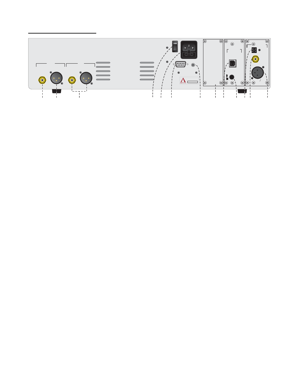
Figure 4 - Rear Panel Layout
1. Right Single-Ended output jack.
2. Right Balanced output jack.
3.
MAIN POWER Switch. Disconnects AC to all circuits. It is recommended that this be left ON at all times
during regular use with the exception of whenever cables are connected/disconnected or when the unit is
not going to be used for an extended period of time.
4. AC POWER INPUT including Chassis FUSE. Replace with same type and rating only. (Spare fuse inside).
5. DB9
RS232 connector. Used for connecting a system control device to the Pandora to control and monitor
its functions.
6. Remote TRIGGER jack. When the STANDBY button is pressed to take the Pandora out of standby, the
rear panel TRIGGER jack becomes active with a 5 VDC signal. A compatible receiving device such as the
Atlas Power amplifier will receive this signal and will change its mode from standby to operate. When the
Standby button is pressed again the signal goes to 0V and puts the receiving device into STANDBY mode.
7. Blank jack plate. This slot can be used for an additional Digital Input board.
8. USB type B Input jack. The USB 2.0 standard specifies a maximum cable length of 16 feet (5 meters). It is
not recommended to use extenders or hubs with the Pandora.
9. Push
SWITCH selects CLASS 1 or 2. Refer to the “USB Audio Input Speed” section on the next page.
10. TOSLINK Input jack.
11. SINGLE-ENDED (RCA COAX) digital Input jack.
12. AES/EBU (XLR) digital Input jack.
10