Electrical connections – Datalogic Scanning DS8100A User Manual
Page 5
DS8100A QUICK GUIDE
5
By configuring the oscillating speed up to the maximum value of 19 Hz, raster emulation can be performed for
reading fast moving objects.
Hz Max.
Aperture
0-5 50°
6-10 30°
11-15 20°
16-19 10°
NOTE
By limiting the raster width to the minimum necessary, the number of scans on the reading
surface is increased.
Electrical Connections:
The details of the connector pins are indicated in the following tables:
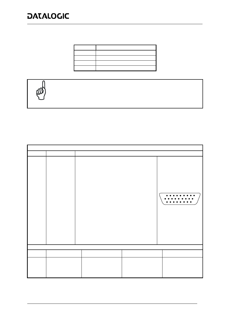
The DS8100A scanner provides a 26-pin male D-sub connector for connection to power supply, Host interface
(Main and Aux), and input/output signals.
26-pin D-Sub Connector Pinout
Pin Name
Function
Chassis - internally connected to GND
1 CHASSIS
Cable shield connected to chassis
20
RXAUX
Receive data of auxiliary RS232 (referred to GND)
21
TXAUX
Transmit data of auxiliary RS232 (referred to GND)
8
OUT 1+
Configurable digital output 1 – positive pin
22 OUT
1-
Configurable
digital output 1 – negative pin
11 OUT
2+
Configurable
digital output 2 – positive pin
12 OUT
2-
Configurable
digital output 2 – negative pin
16 OUT
3A
Configurable
digital
output 3 – polarity insensitive
17 OUT
3B
Configurable
digital
output 3 – polarity insensitive
18 EXT_TRIG/PS
A
External
trigger
(polarity insensitive) for PS
19 EXT_TRIG/PS
B
External
trigger
(polarity insensitive) for PS
6
IN2/ENC A
Input signal 2 (polarity insensitive) for Encoder
10
IN2/ENC B
Input signal 2 (polarity insensitive) for Encoder
14
IN3A
Input signal 3 (polarity insensitive)
15
IN4A
Input signal 4 (polarity insensitive)
24
IN_REF
Common reference of IN3 and IN4 (polarity insensitive)
9, 13
VS
Supply voltage – positive pin
23, 25, 26 GND
Supply voltage – negative pin
10
19
1
18
9
26
26-pin male D-sub Connector
Main Interface Connector Pinout
Pin
RS232
RS485 Full-Duplex
RS485 Half-Duplex
20 mA C.L.
(INT-30 with C-BOX 100 only)
2 TX
TX485+ RTX485+
3 RX
RX485+
4 RTS
TX485-
RTX485-
5 CTS
RX485-
7 GND_ISO
GND_ISO
GND_ISO
see INT-30 instructions