Web-based control application getting connected – Adtec digital EN-40 (version 2.02.24) User Manual
Page 2
Power
To begin, you will need to connect to your EN-40 via ethernet
directly, or by adding the EN-40 to your local area network.The default
address for all Adtec devices is 192.168.10.48.
To connect directly to the device, make sure that your computer
and the device have IP addresses within the same IP class range (ex.
192.168.10.48 for the device and 192.168.10.49 for your computer). If
you need to change the IP address of the device, this can be done via
the front panel, System > Network menu. Using a CAT 5 crossover
cable, connect one end to your computer and the other to the Ethernet
port found on the processor section of the back panel. (Some computers
can auto negotiate the connection and a crossover may not be
necessary.)
To add the device to a LAN, connect a standard CAT 5 Ethernet
cable to your network router and then to the Ethernet port on the back
of the device. If your network is DHCP enabled and you prefer that over
a static IP, you can turn on DHCP for the device via the front panel,
System > Network menu.
Web-Based Control Application
Getting Connected
?
Adtec Digital has adopted zero-configuration
networking technology, streamlining the setup and
configuration processes for our products. The use of
this technology enables automatic discovery of Adtec
devices and services on an IP network. Used in
tandem with the web-based control and configuration
applications we can now provide 1-click access to any
device.
By using the built-in Bonjour
©
locater in Apple's
©
Safari
©
browser or the plug-ins readily available for IE
©
or Firefox
©
browsers, users can locate all of the Adtec
devices on a network by referencing the serial number
on the back of the device. Clicking on the unit in the
Bonjour
©
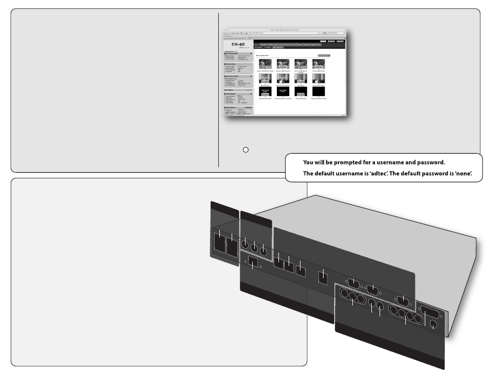
list will re-route you to a login page. If you do
not wish to use Bonjour, you can reach the device’s
web application by pointing your browser to the IP Address of the device. Ex. http://192.168.10.48.
The left panel of the application will report current status in real-time while the right panel tabs will
allow you to configure your device. Additional hints regarding configuration options can be found by clicking on
the hints buttons
associated with each
field or group of fields.
Adtec Digital Technical Support: 615.256.6619 www.adtecinc.com
10.25.10
Power
...............................................................................................................................
Power 1 & 2
Redundant AC Power, Standard 3 pin computer power plug
(Auto range 70-240 VAC Input)
Modulator (optional)*
............................................................................................
Main
RF output, 50 Ohm BNC
L-Band Model: Frequency range 950 MHz to 1.750 GHz, Power Level -50 to -7 dBm
IF Model: Frequency range 50 MHz to 180 MHz, Power Level -30 to +5 dBm
Monitor
RF output, 50 Ohm BNC
L-Band Model: Fixed power level at -45 dBm
IF Model: Fixed power level at -45 dBm, fixed frequency at 1.08 GHz
10MHz Clock
BNC 50 Ohm connector for external 10MHz reference input
Processor
......................................................................................................................
GigE
MPEG2 or RTP multicast transport egress port (SMPTE 2022)
COM2
API Serial Communication Interface
COM1
Serial Port Used for Troubleshooting (Terminal)
Ethernet
10/100 base T ethernet interface (Monitoring/Management)
USB 2.0
Not Currently Supported
DVC Parport
9-pin parallel I/O interface for control systems
RS422
Not Currently Supported
GPIO
Tally and Control Port
Encoder
.........................................................................................................................
ASI OUT
75 Ohm source ASI x3 per EN5000839. Up to 100 Mbps.
CVBS In
75 Ohm terminated Standard Definition Composite Video Input
SDI In
75 Ohm terminated Input, Video & Audio (SMPTE 259M for SD & SMPTE 292M for HD) BNC
AES Audio In 1-4
75 Ohm AES-3 per AES3-2003
AES Audio Out 1
Not Currently Supported
Analog Audio In
Stereo Pairs 1 and 2 (600 Ohm Balanced)
C
OM2
Modulato
r
Processo
r
ASI Out X 3
C
VBS In
SDI In
Enco
der
AES A
udio
In 1-4
D
V
C P
ar
p
or
t
RS422
GPIO
A
nalo
g A
udio
G
igE
AES A
udio Out
M
ain
M
onit
or
10Mhz
C
lo
ck
C
OM1
Ether
net
USB
1
2