Zilog Z8F0130 User Manual
Page 5
Ethernet Smart Cable
User Manual
UM020705-1012
Page 5 of 13
2. Use the Ethernet crossover cable supplied with the Ethernet Smart Cable to connect
the Ethernet Smart Cable to the host PC’s Ethernet port.
3. Connect the 5 V DC power supply to the Ethernet Smart Cable power connector. As a
result, the green PWR and RUN LEDs will illuminate. The green link LED on the
Ethernet Smart Cable’s RJ-45 connector illuminates (see
on page 3), indicat-
ing a live Ethernet connection. The green activity LED on the Ethernet Smart Cable
RJ-45 connector flickers, indicating network activity.
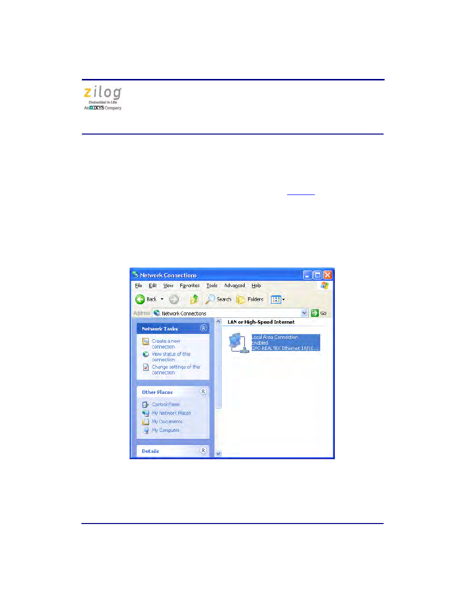
4. On the host PC, open the Windows Control Panel and double-click the
Network and
Internet Connections
icon. The
Network Connections
dialog box will appear, as
shown in Figure 2.
Figure 2. The Network Dialog
- Z8F0131 Z8F0230 Z8F0231 Z8F0430 Z8F0431 Z8F043A Z8F0830 Z8F0831 Z8F083A Z8F1232 Z8F1233 Z8F0113 Z8F011A Z8F0123 Z8F012A Z8F0213 Z8F021A Z8F0223 Z8F022A Z8F0411 Z8F0412 Z8F0413 Z8F041A Z8F0421 Z8F0422 Z8F0423 Z8F042A Z8F0811 Z8F0812 Z8F0813 Z8F081A Z8F0821 Z8F0822 Z8F0823 Z8F082A Z8F0880 Z8F1621 Z8F1622 Z8F1680 Z8F1681 Z8F1682 Z8F2421 Z8F2422 Z8F2480 Z8F3221 Z8F3222 Z8F3281 Z8F3282 Z8F4821 Z8F4822 Z8F4823 Z8F6081 Z8F6082 Z8F6421 Z8F6422 Z8F6423 Z8F6481 Z8F6482 EZ80F91AZA EZ80F91NAA eZ80F92 EZ80F93