XTA 5 Series User Manual
Page 60
Page 60
5 Series
5 Series
5 Series
5 Series Operator’s Manual
All Pass Filter
InA Input A APF:1
InA Input A APF:1
InA Input A APF:1
InA Input A APF:1
0
0
0
0
1k00Hz Q=3.0 Allpass
1k00Hz Q=3.0 Allpass
1k00Hz Q=3.0 Allpass
1k00Hz Q=3.0 Allpass
Remember – to change filter types, press BYPASS
BYPASS
BYPASS
BYPASS to bypass
the filter, and then use ENTER
ENTER
ENTER
ENTER to select the filter type.
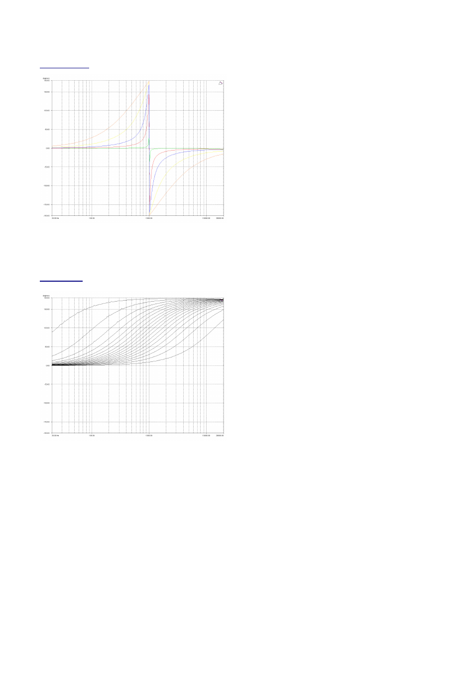
The allpass filter has adjustable frequency and ‘Q’ (or
Bandwidth) controls. These affect the frequency at which the
phase effectively flips 180°, and the ‘speed’ at which this
transition occurs.
The graph shows an allpass filter centred at 1kHz, with various
‘Q’ settings – the higher the ‘Q’ the faster the transition.
Phase Filter
InA Input A PHS:1
InA Input A PHS:1
InA Input A PHS:1
InA Input A PHS:1
0
0
0
0
1k00Hz 150
1k00Hz 150
1k00Hz 150
1k00Hz 150
°°°°
Phase
Phase
Phase
Phase
Remember – to change filter types, press BYPASS
BYPASS
BYPASS
BYPASS to bypass
the filter, and then use ENTER
ENTER
ENTER
ENTER to select the filter type.
The phase filter has adjustable frequency, and phase shift
controls. This introduces a phase shift that gradually changes
from 180° above the centre frequency to the specificed value
at the centre frequency, and tending towards 0° below the
centre frequency.
This graph shows the phase shift relative to the input (ignoring
processing delays), in 10° steps – the filter will actually provide
higher resolution than this, operating in 2° steps.The filter is
centred at 1kHz in this example.