Bandpass filter, Notch filter – XTA 5 Series User Manual
Page 59
✁
✂
✄
☎
✂
✆
✁
✂
✄
☎
✂
✆
✁
✂
✄
☎
✂
✆
✁
✂
✄
☎
✂
✆
Operator’s Manual
Page 59
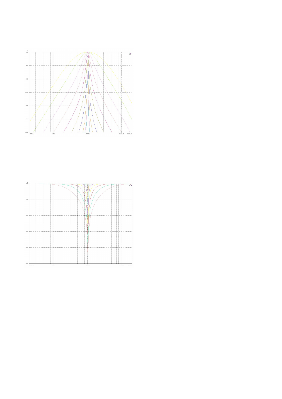
Bandpass Filter
InA In
InA In
InA In
InA Input A BPS:1/
put A BPS:1/
put A BPS:1/
put A BPS:1/\
\
\
\
1k00Hz Q=3.0 Bandpass
1k00Hz Q=3.0 Bandpass
1k00Hz Q=3.0 Bandpass
1k00Hz Q=3.0 Bandpass
Remember – to change filter types, press BYPASS
BYPASS
BYPASS
BYPASS to bypass
the filter, and then use ENTER
ENTER
ENTER
ENTER to select the filter type.
The bandpass filter has adjustable frequency and‘Q’ (or
Bandwidth) controls. These affect a range of frequencies
symmetrically about the centre freqency as shown in the
graph, gradually cutting the level, but providing no gain.
Remember that ‘Q’ is 1/Bandwidth, so the higher the ‘Q’, the
lower the Bandwidth, and the smaller the range of frequencies
affected.
Note that the response is fundamentally NOT a flat-topped
response (so it is not constructed from a high pass and low pass). See previous page for details of how to construct a flat-
topped filter response.
Notch Filter
InA I
InA I
InA I
InA Input A NOT:1
nput A NOT:1
nput A NOT:1
nput A NOT:1\
\
\
\/
/
/
/
1k00Hz Q=0.75 Notch
1k00Hz Q=0.75 Notch
1k00Hz Q=0.75 Notch
1k00Hz Q=0.75 Notch
Remember – to change filter types, press BYPASS
BYPASS
BYPASS
BYPASS to bypass
the filter, and then use ENTER
ENTER
ENTER
ENTER to select the filter type.
The notch filter has adjustable frequency and ‘Q’ (or
Bandwidth) controls. These affect a range of frequencies
symmetrically about the centre freqency as shown in the
graph.
Remember that ‘Q’ is 1/Bandwidth, so the higher the ‘Q’, the
lower the Bandwidth, and the smaller the range of frequencies
affected. The notch filter depth varies with bandwidth – the
wider the filter, the lower the depth will be.