Vectronics VEC-1220K User Manual
Page 26
VEC-1220K/1230K/1240K/1280K Owner's
Manual
24
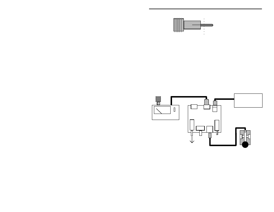
Cut pin here and round off end.
Test Set-up and Procedure:
To test your transmitter, set up as shown in the following diagram. Make sure
the PC board is on a clean non-metallic surface and that the test area is free of
lead-clippings, hardware, and other conductive debris that could get under the
board and cause a short circuit. Before connecting the power supply, make sure
the transmitter power switch (SW1) is turned OFF (out position). The crystal
selector switch (SW2) should be set for Y1 (out position). No direct connection
should be made to your receiver during the initial test. However, your station
receiver should be turned on, placed in the CW mode, and tuned in to the
transmitter's approximate frequency . If any of the steps outlined below fail,
refer to the "In Case of Difficulty" section of the manual.
RF Wattmeter
Dummy Load
Patch Cable
Power Supply
Key
J1
J2
J3
ANT
PWR
KEY
REC
J4
Crystal
Select
Power
VXO
(out)
Switch
1. Press power switch SW1 to ON. There should be no RF output indication.
2. Confirm the crystal select switch is in the out position, selecting crystal Y1.
3. Press the key. The power meter should indicate output of 1 watt or more.
4. Release the key--the output power should drop to zero.
5. Press the crystal select switch to the in position and key. There should be no
output.
6. Return the crystal select switch to the out position.