Vectronics SWR-66 User Manual
Page 5
SWR-66 Dip Meter Adapter
Owner's Manual
5
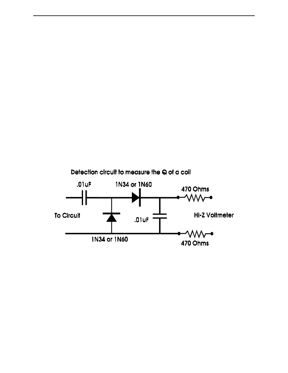
Measure the Q of a coil.
To measure the Q of a circuit you must add a detector circuit, see the figure below, and couple it
the SWR Analyzer (this may slightly alter the Q of the circuit.) Relative Q can be observed by
noting the steepness of the dip as you change frequency. A sharp deep dip at resonance is an
indication of high Q. A wide shallow dip at resonance is an indication of a low Q.
1. Connect a high impedance digital voltmeter across the test circuit in the figure below.
Use the lowest range of the voltmeter.
2. Couple the SWR Analyzer to the tank circuit. Adjust the Tune control for a maximum
voltage reading on the voltmeter. Do not change the coupling during the rest of the test.
Record this frequency as F0.
3. Find a point above and below F1 that the voltage is at 70 % of its max. Record these
frequencies as F1 and F2.
4. Divide the positive difference between F1 and F2 by F0 to get Q.
TECHNICAL ASSISTANCE
If you have any problem with this unit first check the appropriate section of this manual. If the
manual does not reference your problem or your problem is not solved by reading the manual you
may call VECTRONICS at 601-323-5800. You will be best helped if you have your unit,
manual and all information on your station handy so you can answer any questions the
technicians may ask.
You can also send questions by mail to VECTRONICS, 1007 HWY 25 South, Starkville, MS
39759 or by Fax to 601-323-6551. Send a complete description of your problem, an explanation
of exactly how you are using your unit, and a complete description of your station.