Test configurations, Typical application circuit, Design considerations – Delta Electronics DNQ12 User Manual
Page 6: 100 ) ( ч ч ч = ii vi io vo, Input source impedance, Safety considerations
DS_DNQ12SIP25_07172008
6
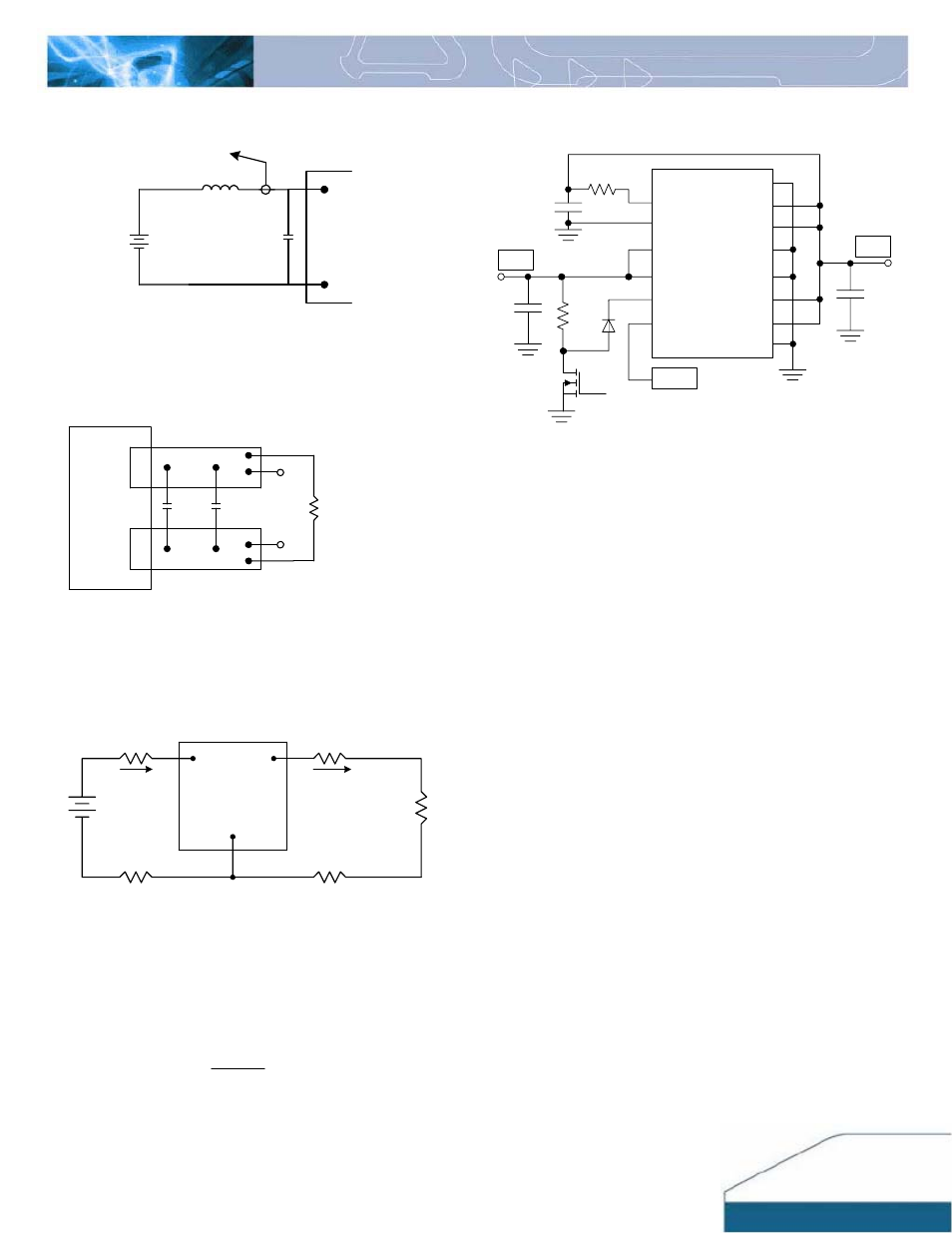
TEST CONFIGURATIONS
Vin(+)
GND
BATTERY
Ls
TO OSCILLOSCOPE
1µH
150µF
Min
Cin
Note: Input reflected ripple current is measured with a
simulated source inductance (Ls) of 1
μH. Current
is measured at the input of the module.
Figure 15:
Input reflected ripple current test setup
Vo
GND
COPPER STRIP
10µF
tantalum
1µF
ceramic SCOPE
Resistive
Load
Note: Use a 10μF tantalum and 1μF capacitor. Scope
measurement should be taken by using a BNC
connector.
Figure 16:
output ripple and noise, start-up transient test setup
SUPPLY
Iin
Vin
Vo
GND
Io
LOAD
CONTACT AND
DISTRIBUTION LOSSES
CONTACT RESISTANCE
Figure 17:
Output voltage and efficiency test setup
Note: All measurements are taken at the module
terminals. When the module is not soldered (via
socket), place Kelvin connections at module
terminals to avoid measurement errors due to
contact resistance.
%
100
)
(
Ч
Ч
Ч
=
Ii
Vi
Io
Vo
η
TYPICAL APPLICATION CIRCUIT
SENSE+
VOUT
VIN
VIN
VOUT
VOUT
VOUT
GND
GND
GND
GND
SENSE -
ENA
SHARE
1
2
3
12
14
13
10
11
6
7
8
9
4
5
Rtrim
1uF
Rx
Qx
4.99k
Dx
Vin
Vout
SHARE
Cin
Cout
Figure 18:
Application Schematic
DESIGN CONSIDERATIONS
Input Source Impedance
The power module should be connected to a low
ac-impedance input source. Highly inductive source
impedance can affect the stability of the module. The
input capacitor Cin should be placed close to the module
input pins and in equal from the two input pins of the
module. To filter ripple current and ensure module
stability in the presence of inductive source impedance,
Cin is recommended to be 150µF minimum and with an
adequate RMS Current Rating to sustain ripple voltage
of 50mV RMS at 1MHz.
When using multiple modules in parallel, a small
inductor (0.2 – 0.5µH) is recommended at the input of
each module to prevent interaction between modules.
Consult Delta for more technical support.
Safety Considerations
For safety-agency approval the power module must be
installed in compliance with the spacing and separation
requirements of the end-use safety agency standards.
For the converter output to be considered meeting the
requirements of safety extra-low voltage (SELV), the
input must meet SELV requirements. The power module
has extra-low voltage (ELV) outputs when all inputs are
ELV.
The input to these units is to be provided with a
maximum of 30A fast-acting fuse in the ungrounded
lead.