Menu operations, 8] audio, 9] system – TVLogic SWM-170A User Manual
Page 15
28 Multi Format LCD Monitor
Multi Format LCD Monitor 29
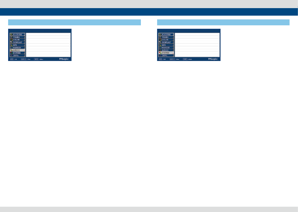
[8] AUDIO
5. Menu Operations
●
LEVEL METER SELECT
- Used to control the Embedded Audio Level
Meters.
- Available modes are OFF, G1+G2, G2+G3,
G3+G4, G1+G3, G1+G4,G2+G4 and 16CH.
- If Main Menu window activates, the level
meter displays semi-transparent even if
[LEVEL METER SIZE] menu is set to Normal.
It returns to normal when the Main Menu
window is deactivated.
●
LEVEL METER DISPLAY
- Used to control display method of Audio
Level Meters.
- Available modes are Pair and Group.
●
LEVEL METER REFERENCE
- Used to set audio level default.
- Available values are -18dB and -20dB.
- Audio within selected value is displayed in
green and exceeded audio level is displayed
in yellow.
- Audio exceeding -4dB is displayed in red.
●
LEVEL METER DECAY TIME
- Used to set the reduction time of the
maximum indication of audio signals.
- Available values are form 0 to 31. Larger
values indicate a longer time to display.
●
LEVEL METER SIZE
- Used to control the size of the Audio Level
Meters.
- Available modes are SMALL, SMALL TRANS,
NORMAL, NORMAL TRANS, LARGE and
LARGE TRANS.
- In SMALL, NORMAL and LARGE modes, the
Audio Level Meter appears opaque.
- In SMALL TRANS., NORMAL TRANS and
LARGE TRANS modes, the Audio Level Meter
appears semitransparent.
SWM-170A
SDI A
LEVEL METER SELECT
LEVEL METER DISPLAY
LEVEL METER REFERENCE
LEVEL METER DECAY TIME
LEVEL METER SIZE
LEVEL METER POSITION
OFF
PAIR
-20dB
O
SMALL
HOR.
●
LEVEL METER POSITION
- Used to control the position of the Audio
Level Meters.
- Available values are HOR, VER and BOT.
1080/60i
SWM-170A
SDI A
●
USER CONFIG SET
- Used to save and apply three kinds of user
configuration.
- Available modes are USER1, USER2 and
USER3.
- Effective items for each USER1, USER2
and USER3 settings are [MARKER] menu of
MARKER, CENTER MARKER, SAFETY AREA,
MARKER MAT and MARKER COLOR
and [PICTURE] menu of , BRIGHT, CONTRAST,
CHROMA, PHASE and APERTURE.
●
SERIAL NUMBER
- Displays the serial number of the monitor.
●
LOCK ENABLE
- Factory use only.
●
OSD DISPLAY
- Used to control the OSD display time.
- Available values are 3 SEC, 20 SEC and
CONTINUE.
●
OSD POSITION
- Controls the OSD position.
- Available positions are CENTER, Top-
Right(R-T), Bottom-Right(R-B), Bottom-
Left(L-B) and Top-Left(L-T).
●
INTERNAL PATTERN
- This item generates internal white pattern.
- The white level select between 0% and 100%
(Per 5% increase or decrease)
●
SET DEFAULT
- User can use SET DEFAULT menu to initialize
to factory setting.
●
SIGNAL LOCK
- Used to enable/ disable the synchronization
of input signal.
- ENABLE : Displays the video by using the
synchronization of input signal.
- DISABLE : Displays the video by locally
generated synchronization. The monitor
responses rapidly when the input signal or
format is changed. (The video may loss or
cut.)
[9] SYSTEM
5. Menu Operations
PAGE I >> PAGE II
USER CONFIG SET
SERIAL NUMBER
OSD DISPLAY
OSD POSITION
INTERNAL PATTERN
SET DEFAULT
SIGNAL LOCK
USER 1
XXXXXXXXXXXXX
CONTINUE
CENTER
OFF
ENABLE
1080/60i