Oxygen sensor installation (autotune), Fxd tips, Step 4 – ThunderMax Models w/96”Engine ARB EO # K-001 User Manual
Page 3
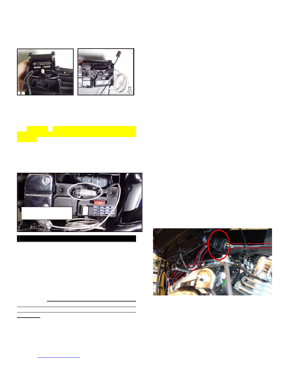
sensor harnesses should exit towards the opposite side
of the caddy.
FXD-D: Before reinstalling the caddy, feed the front
cylinder oxygen sensor harness through to the right side
of the bike, over the top and to the rear of the starter
motor. Reinstall the caddy with fuse and relay blocks in
place. Reconnect the TSSM, coil and ECM harnesses
and main fuse. If equipped with AutoTune, plug the
closed loop module into the 4-pin gray data link on
the bike. It is through the data port that data from the
AutoTune module is transferred to the ThunderMax. A
‘Y’ harness is available (# 309-343) to keep an open
data port if desired. After programming and setup, the
communication cable can be coiled up and kept under
the caddy cover if not using the ‘pigtail’ harness.
Oxygen Sensor Installation (AutoTune)
Install supplied wide band oxygen sensors in the front
and rear exhaust pipes. Unplug and remove the stock
narrow band oxygen sensors and replace with the
supplied wide band units. The wide band sensors are
longer than the factory sensors. Installation of the wide
band sensors into factory headpipes presents no
clearance problems, however, some aftermarket pipes
may require exhaust pipe modification or sensor bung
relocation for interference-free installation. The sensors
must mount freely without contacting surrounding
components. If this is not possible, do not attempt to
bend or modify the sensor in any way as it is a
sensitive electronic component and will be damaged
if you do. Modify the pipe if required for clearance.
Weld-in bungs are available for exhausts systems not
equipped with bungs or if current bungs present
clearance issues. Bungs should be located no more
than 3-4” from the head/pipe connection (for ideal
location, refer to the factory location on 2007-up
models). Weld-in bungs are available from Zipper’s
(#272-200, straight; #272-202, angled). After
installation, route the sensor harness away from the
engine and along the frame when possible, above the
lowest frame point to avoid the possibility of dragging
ground during operation. Avoid routing harnesses where
engine movement or moving parts can contact and
damage the harnesses or connector plugs.
Connect the sensors to the closed loop module. The
AutoTune harness for the rear cylinder sensor is shorter
and can be easily identified by black tracers on all of its
wires; both plugs are clearly marked for front and rear
use. It is very important to install these correctly or the
engine will perform poorly! Tie the harnesses to the
frame or existing component harnesses, taking care to
avoid contact with any vibrating component that may
chaff the sheathing or wires. Some disassembly of bike
components may be required for best harness routing.
FXD Tips:
The rear harness mounts easily, just coil
the excess wires and locate them above the
transmission. To install the front harness, remove the
rear gas tank mounting bolts and loosen the front
mounting bolt. Lift the gas tank from the rear, pivoting it
on the front bolt. Prop the tank up with a block of wood,
exposing the frame backbone. The front harness should
travel from the AutoTune module, along the left side of
the frame backbone with the oxygen sensor connector
plug positioned just above the top engine mount. After
installing and tightening the sensor, route the sensor
lead up along the left front downtube to the frame
backbone and complete the connection to the AutoTune
harness. View the connector position with the gas tank
in place and tie the wires to the frame; once you have
verified gas tank/motor mount clearance, re-tighten tank.
Dyna®: ECM installed with
communication cable attached.
Step 4
Load a Base Map to your SmartLink software.
Selecting a base map for your ThunderMax is easy
thanks to the filtering system in the SmartLink software.
Open SmartLink; from the toolbar choose [EFI Maps]
[EFI Map Listings / Definitions]. You should first
update the Map Definitions file to ensure you have the
latest available maps. [Close] the [Base Map
Definitions] window, then click the [Check Internet For
www.Thunder-Max.com
309-375 Installation / Setup Guide V2009.10.30 [email protected]
3