ThunderMax PN#309-385 - GenII Sportster User Manual
Installation / setup guide
www.Thunder-Max.com
309-385 Installation / Setup Guide V2012.06.28
1
Part # 309-385 for
2010-2012 XL Models
2004-2011 Dyna® Models
2008-2010 Softail® Rocker Models
2009 CVO Springer FXSTSSE
2
Thank you for purchasing a ThunderMax ECM!
Please read through the following instructions before
beginning the installation procedure. Following these
instructions will ensure that the ECM is installed and
setup properly for optimal results. If you have any
problems or questions, please refer to the SmartLink
Tuning .pdf Manual, included on the CD (Help Menu)
with this package. The cable included with your
ThunderMax requires a serial port on your computer for
communication with the ThunderMax. If you do not have
a serial port on your computer, you will need to use a
USB to Serial converter. Record serial number NOW
on your warranty card, and here for your records!
ECM Serial # TMFM____________________________
AutoTune Serial # TMAT________________________
Step 1
Insert the SmartLink
CD
into
your
computer.
SmartLink will automatically
open the InstallShield Wizard
when the computer finds the
CD-Rom.
Follow
the
instructions and install the
software on your computer.
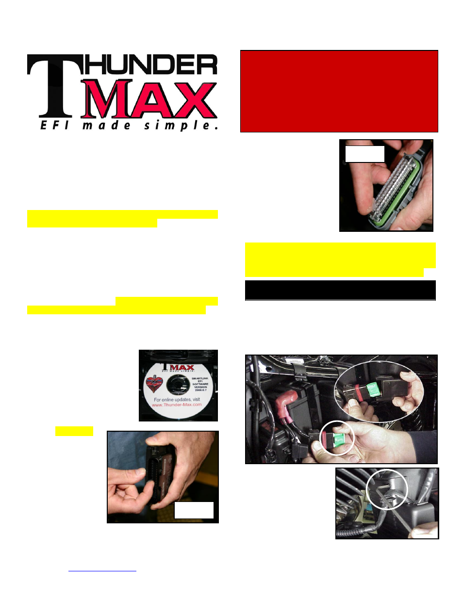
Step 2
All Models
–
A packet of dielectric
grease is included
with
your
ThunderMax. When
installing the ECM,
apply the provided
dielectric grease to
the inside lip of the
ThunderMax
ECM
(Photo 1) and
across the clear case on
the
36
pin
ECM
connector
(Photo
2).
Spread the grease across
all of the female terminal
openings, making sure
the grease penetrates
openings. This grease
will greatly improve vital
conductivity between the
ThunderMax and the 36
pin connector.
Remove any previously installed ancillary tuning
device including oxygen sensor eliminators that may
be plugged into the factory oxygen sensor harness.
Check battery cable terminals (clean and tighten).
XL Sportster® Models
(Skip ahead for Dyna® or Rocker® Models)
XL-A: Remove the left side cover to expose the battery
and main fuse compartment. Remove the main fuse
cover, then the main fuse (Note: if equipped with
optional security system, turn on ignition switch before
you remove the fuse to avoid tripping alarm).
XL-B:
Remove the
socket head screw and
slide the ECM cover
towards the left side of
the bike to remove it
(remove
wires
from
ECM
caddy
cover
channels).
Installation / Setup Guide
Please Note: This product is Legal in California
only for racing vehicles which may never be used
upon a highway.
The user shall determine suitability of the
product for his or her use. Installation and use on a pollution-
controlled vehicle constitutes tampering under the U.S. EPA
guidelines and can lead to substantial fines. Review your
application and check your local laws before installing.
Photo 1
Photo 2