Fxd (dyna®) models – ThunderMax Models w/96”Engine ARB EO # K-001 User Manual
Page 2
www.Thunder-Max.com
309-375 Installation / Setup Guide V2009.10.30 [email protected]
2
ST-B: Remove the bolts holding the fuse block bracket
to the frame and lift the bracket away from the frame to
allow access to the gap between the frame and oil tank
on the right side of the motorcycle.
ST-C: Connect the ThunderMax ECM to the harness
and position it loosely in the ECM tray. Feed both
oxygen sensor harnesses (front cylinder first) through
the gap between the frame and oil tank on the right side
of the motorcycle.
ST-D: At this time you may want to snake the rear
oxygen sensor towards the rear exhaust pipe by starting
it from the right side of the bike, under the oil tank, and
around the seat post to the rear exhaust position (do not
connect it to the harness until after it has been installed
and tightened into the exhaust pipe, so the harness can
turn freely). Ensure that the rear O
2
harness plug is
positioned closer to the swingarm pivot bolt so it will not
be crushed between the upper swingarm and the oil tank
at full stroke (suspension bottomed).
ST-E: Position the harness plug for the front pipe under
the transmission, along the frame rail. Install the oxygen
sensors into the exhaust pipes, connect the harness
plugs to the oxygen sensors and secure the harnesses
to the frame (above the lowest point) with wire ties.
ST-F: Re-install the fuse block
bracket bolts and attach the
ThunderMax 50 ECM to the ECM
tray. Re-install the battery (positive
cable first) and install the ECM fuse.
Plug the AutoTune module into
the 4-pin gray data port plug on
the motorcycle.
FXD (Dyna®) Models
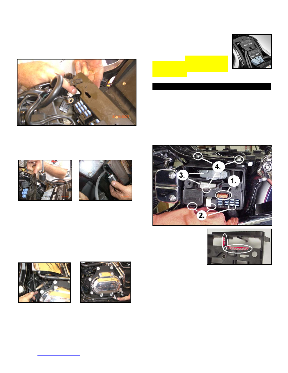
FXD-A: Remove the left side cover to reveal the
electrical caddy. Remove the main fuse (1). Use a
small screwdriver to release the catches holding the fuse
block, relay block and TSSM module to the electrical
caddy (2). Unplug the main harness from the ECM and
remove the data plug from its holder (3). Remove the 2
hex head and 1 socket head mounting bolts to free the
caddy for removal (4). Unplug the plug wires and
harness from the coil and remove the caddy.
FXD-B: Remove the
stock ECM from the
electrical caddy. The
caddy must be slightly
modified for additional
main harness
connector clearance.
Use a Dremel or Roto-Zip tool to provide additional
clearance for the harness plug catch; also remove
approximately 3/8” from the partition support as shown.
FXD-C: Because of the impossibility of connecting the
communication cable without disassembly once
assembled on FXD models, the cable should be
permanently installed to the ThunderMax, or the optional
‘pigtail’ harness mentioned in step 2 used. If using the
communication cable, feed it and the AutoTune power
harness through the ECM plug port of the caddy and
mount the ECM to the caddy as shown. The oxygen