Installation and operation – Pinnacle Systems NSD User Manual
Page 15
10
Installation and Operation
NSD Safety Mat System
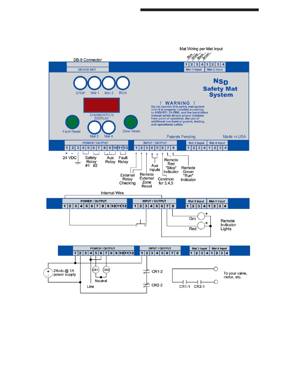
NSD-DR-04 (DIN-rail Controller with diagnostics)
NOTE: Terminal #6 (INPUT/OUTPUT PLUG) is internally connected to Terminal #1 (POWER/OUTPUT)
plug. This allows Terminal #6 to provide +24v to the lights for the RSD (Remote Status Display).
REMOTE STATUS DISPLAY
Green:
Terminal #8 (INPUT/OUTPUT)
Red:
Terminal #7 (INPUT/OUTPUT)
Black:
Terminal #1 (POWER/OUTPUT)
White/Black:
Terminal #3 (INPUT/OUTPUT) / Terminal #2 (POWER/OUTPUT)
12cond cable:
J1 (on left side of diagnostics display)
External Relay Checking (optional usage)
NOTE: Canadian market wiring is black, red, red, black with 18-guage wiring size.