Wall-mount – KBC Networks ESUL4-FL1 User Manual
Page 8
Ethernet Switch User Manual
Manual-ESUL4-FL1_Series
_
HW-Rev0611B
Copyright © KBC Networks Ltd.
Page 8 of 17
www.kbcnetworks.com
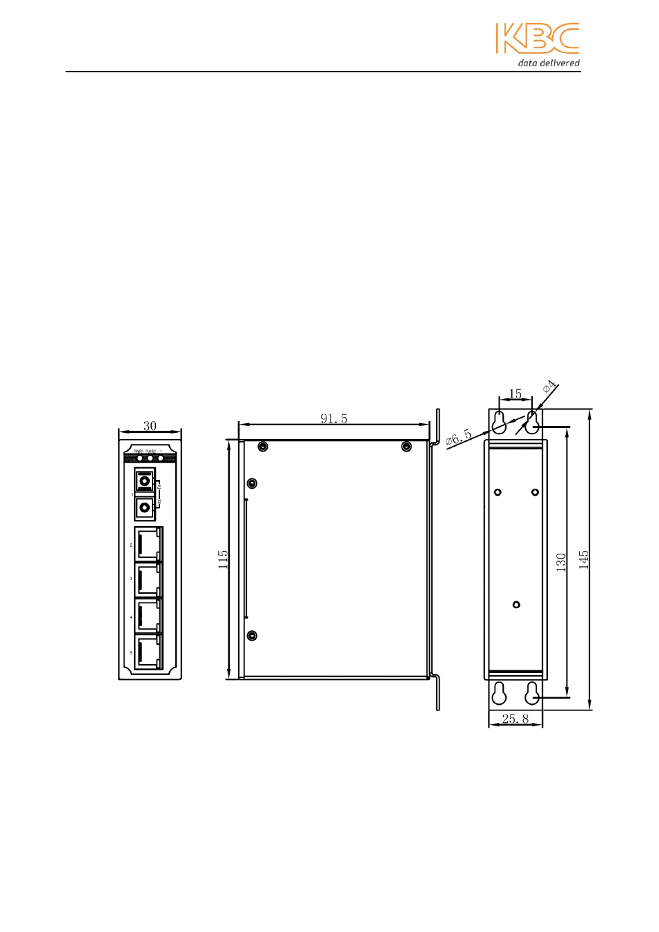
2.3.2 Wall-mount
Remove all packaging material.
Unscrew the DIN rail mounting plate from the switch taking special care to
retain the 2 screws using a Phillips No.1 or No.2 screwdriver.
Attach the supplied wall mount plate to the switch using the 2 screws that
have just been removed from the DIN rail mounting plate with a Phillips
No.1 or No.2 screwdriver.
Position the unit on the required, flat surface and secure with screws via the
mounting plate holes. Screws are not provided.
Attach copper and/or fiber cables as required.
Insert the male power block (attached to the supplied in-line PSU) to the
female power socket on the device and tighten the terminal locking screws
using the flathead screw driver provided.
See Section 2.7 for LED status.
Figure 2.2 Dimensional drawings for wall mounting (mm)
- FTL1-S1A-B-MSE (10 pages)
- MCG1-S2-BS (8 pages)
- ThruLink SP (2 pages)
- VPS Solar Power Kits (12 pages)
- MiniLink (15 pages)
- Mesh2HT (59 pages)
- MeshII (2 pages)
- WES (19 pages)
- WES (18 pages)
- WES2HT 17dBi Point-to-Point Client / Host 5GHz (2 pages)
- WES2HT 2/5dBi Point-to-Multipoint Host with PoE (2 pages)
- WES2HT 9dBi Multipoint Host (2 pages)
- WESII 9dBi to 9dBi Kit (5 pages)
- WESIIKT V221 17dBi to 17dBi Kit (4 pages)
- H.264 Encoder (2 pages)
- H.264 Encoder (49 pages)
- MPEG-4 Decoder (2 pages)
- MPEG-4 Encoder (2 pages)
- MPEG4 Decoder (29 pages)
- MPEG4 Encoder (33 pages)
- WES2HT (142 pages)
- ESML3-FL2-D4 (18 pages)
- ESUL6-FL2 (20 pages)
- ESML6-FL2 (64 pages)
- ESML6-P3 (49 pages)
- ESML6-P3 (51 pages)
- ESML6-P3 (17 pages)
- WESII (141 pages)
- ESUG4P-PG2 (15 pages)
- ESUG8P (14 pages)
- ESUL5 (15 pages)
- ESML8P-PC2 (110 pages)
- ESUL8 (14 pages)
- ESUL5P (14 pages)
- EE2CL (19 pages)
- ESUL8P-PC2 (15 pages)
- EE1CL (17 pages)
- EE1R3 (12 pages)
- FCHA1-M1T-R-WSB (13 pages)
- FDVA2-S2T-R-WSC (11 pages)
- Compact Transceiver (36 pages)
- FDVA4-DB1-S1T-R-WSC (14 pages)
- 3U Chassis Transceiver (40 pages)
- FDVA4-S1T-R-WSC (11 pages)