Hardware, Hardware description, Fig. 2.1.1. – block diagram of the generator – Dataman 530 Series User Manual
Page 9
DATAMAN 530 series AWG
User’s Guide
2. Hardware
The information contained in this chapter will help you understand features of your
device.
2.1. Hardware description
The 530 series arbitrary waveform generator connects to computer via USB 2.0. The
device accuracy is assured by the stability of the circuits and by the calibration
constants stored directly in the device.
The output waveform of can defined by a maximum of 16384 samples with 12 bits
resolution. The generator is equipped with two outputs. The output range of low level
output (L) is +– 4.5V with an output resistance of 50 Ohm. It is calibrated for up to 10
MHz. The high level output (H) offers +- 25V voltage range, with 600 Ohm
resistance. It is calibrated for up to 200kHz.
HA
PH
LA
AC
HD
AF
VS(11:0)
DN/
FL(3:0)
DAC
VA(11:0)
M
MD(11:0)
WAC
RCD
WA(13:0)
AK(12:0)
AS(12:0)
RCN
RA(13:0)
CLD
PLL1
RF(15:0)
DSC
DL(1:0)
CX(6:0)
clk
CNT
L
H
SO
SI
HON
PLL2
QF(15:0)
SW
SQ
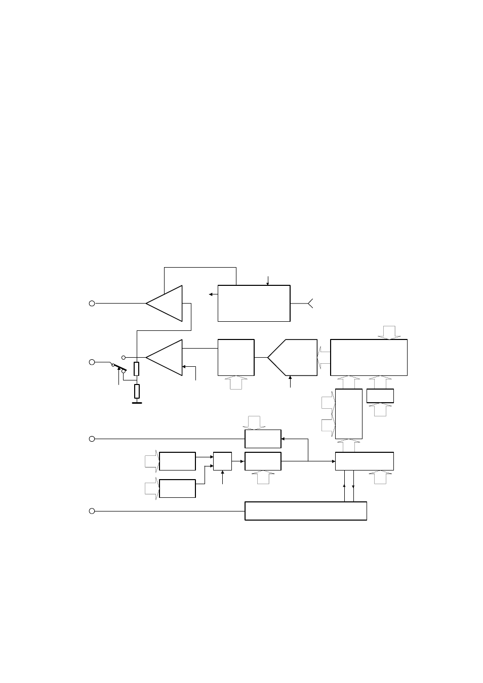
Fig. 2.1.1. – Block diagram of the generator
The block diagram of the generator is on the picture 2.1.1. The output amplifier LA is
connected to attenuator with settable attenuation of 0 or 20dB. The output of this
attenuator is connected to the output connector. The LA output amplifier together with
HA output amplifier are controlled by the output of the fast DA converter (DAC) via
low pass filter with settable cut-off frequency (AF). The samples of the output
waveform are stored in local storage (M) of the generator. The sample handling is
provided by (CNT, DSC, CLD, RCN, RCD, WAC) modules. They are clocked by
- 9 -