Diamond Systems C-PGS-KIT User Manual
Page 5
Pegasus Fast Start Guide
7460572 Rev A
Page 5 of 12
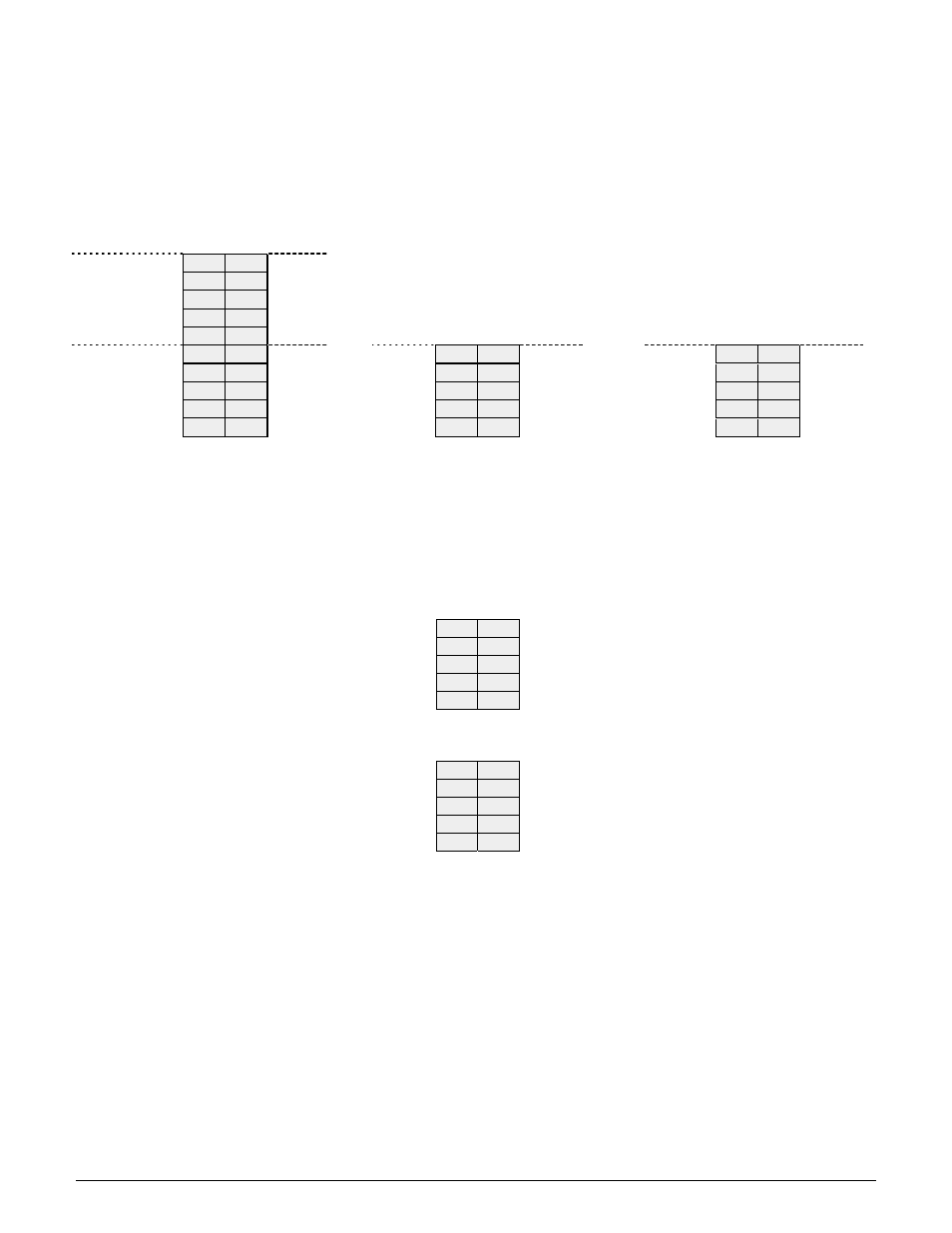
SERIAL PORT CONNECTOR (COM1)
This connector provides access to the 2 serial ports from the CPU chip. Port 1 is RS‐232 only and Port 2
may be jumper‐configured for RS‐232, RS‐422 or RS‐485 protocols. In RS‐422/485 mode, the port may
have a jumper‐selectable 120‐ohm termination resistor across the RX pins and jumper‐selectable pull‐
up/pull‐down resistors on the TX/RX lines. The RX resistors are configured so that the port reads back a
0 when it is open circuit.
RS‐232 Configuration
RS‐422 Configuration
RS‐485 configuration
Port 1
DCD 1
1
2
DSR 1
RXD 1
3
4
RTS 1
TXD 1
5
6
CTS 1
DTR 1
7
8
RI 1
Ground
9
10
Ground
Port 2
DCD 2
11
12
DSR 2
NC
11
12
NC
NC
11
12
NC
RXD 2
13
14
RTS 2
TX+
13
14
TX‐
RTX+
13
14
RTX‐
TXD 2
15
16
CTS 2
RX+
15
16
RX‐
NC
15
16
NC
DTR 2
17
18
RI 2
NC
17
18
NC
NC
17
18
NC
Ground
19
20
Ground
Ground
19
20
Ground
Ground
19
20
Ground
USB CONNECTORS (USB1 and USB2)
These connectors provide access to the four USB 2.0 ports. The shield pin is tied to system ground. The
key positions are missing to match the key position in the cable to prevent misconnection. Both
connectors have the same pin out.
Ground
1
2
+5V
Channel 0 Data+
3
4
Channel 0 Data ‐
Key
5
6
Ground
Ground
7
8
+5V
Channel 1 Data+
9
10
Channel 1 Data ‐
Ground
1
2
+5V
Channel 2 Data+
3
4
Channel 2 Data ‐
Key
5
6
Ground
Ground
7
8
+5V
Channel 3 Data+
9
10
Channel 3 Data ‐