Powering on pegasus, Bios configuration for add‐on boards – Diamond Systems C-PGS-KIT User Manual
Page 10
Pegasus Fast Start Guide
7460572 Rev A
Page 10 of 12
POWERING ON PEGASUS
Follow these steps to power on and verify the functionality of the Pegasus SBC. This process assumes
you have a Pegasus SBC and cable kit.
1. Connect a VGA monitor to the SBC. Attach the VGA cable, 6981084, to the VGA connector on the
SBC and connect your monitor VGA cable to the DB9 socket.
2. Connect a keyboard and mouse to the SBC. Attach the PS/2 Keyboard/Mouse cable, 6981162, to
the PS/2 connector on the SBC and connect your keyboard and mouse devices to the connectors
on the other end of the cable.
3. (Optional for USB Keyboard/Mouse) If you are using a USB keyboard and mouse, attach the USB
cable, 6981171, to the USB0‐1 connector on the SBC and connect your keyboard and mouse
devices to the connectors on the other end of the cable.
4. Connect an external IDE hard drive or CD device to the SBC. Attach the IDE ribbon cable,
6981004, to the IDE/Flashdisk connector on the SBC and connect your IDE device to the
connector on the other end of the cable. Note: you must provide an external source of power
for your IDE device.
5. (Optional for USB storage device) If you are using a USB storage device, attach the USB cable,
6981171, to the USB0‐1 (USB2‐3 if using a USB keyboard and mouse) connector on the SBC and
connect your external storage device to the USB0 (USB2 if using a USB keyboard and mouse)
connector on the other end of the cable.
6. Connect the SBC to power. Attach the Power In cable, 6981175, to the Power In connector on
the SBC. Ensure your +5V power source is off. Connect your +5V power source to the other end
of the cable.
7. Turn on the power source.
The Pegasus BIOS screen should appear and then the SBC should begin booting from the external
storage device.
BIOS CONFIGURATION FOR ADD‐ON BOARDS
When you plug PC/104 boards onto Pegasus, the BIOS may or may not recognize the new board. If the
new board is not recognized, you may need to configure the new hardware in the BIOS before being
able to use it. You can configure the system’s IRQ/DMA resources from the BIOS’s PnP/PCI
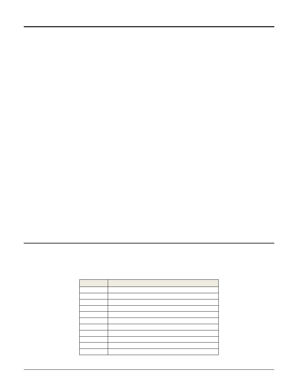
Configurations screen. Following is a table of the IRQs for the system peripheral devices.
IRQ Level Function
IRQ 01
PC/AT Enhanced PS/2 Keyboard
IRQ 03
Communications Port
IRQ 04
Communications Port
IRQ 05
Standard Enhanced PCI to USB Host Controller
IRQ 05
Standard Open HCD USB Host Controller
IRQ 06
Standard Floppy Disk Controller
IRQ 10
Advanced Micro Devices Win 2K/Win Graphics Driver
IRQ 10
Geode LX AES Crypto Driver
IRQ 11
Realtek RTL8139/810x Family Fast Ethernet NIC
IRQ 12
Microsoft PS/2 Mouse
IRQ 14
Primary IDE Channel