System connection by cuering, Overview – CUE smartCUE User Manual
Page 6
User Manual Interfaces
www.cuesystem.com
Page 6 of 44
3. System Connection by CUEring
3.1. Overview ....................................................................
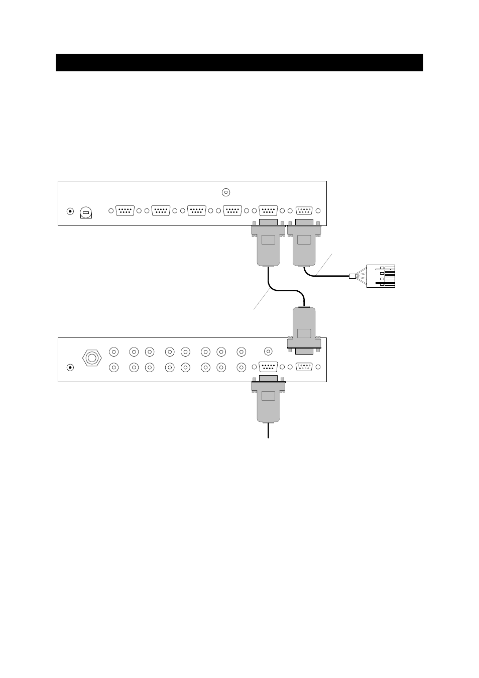
All interfaces are connected to the system via CUEring. It is a RS-232 serial channel dedicated for
system commands transmission.
First interface is connected to the control unit Assistant or Assistant-S by CUEring Cable /a. Further
interfaces are connected by Control Cable 9-pin - see picture below.
GND
DATA OUT
DATA IN
DC IN
24V
CHANNEL A
CHANNEL B
CHANNEL C
CHANNEL D
FUSE
1 A
GND
DATA OUT
DATA IN
A
4
3
2
1
D
C
B
INPUTS
OUTPUTS
DC IN
24V
MIC
Assistant or Assistant-S
CUEring output
CUEring Cable /a
Control Cable 9-pin
or
O-ring Cable
To other interfaces
1
4
3
2
The connector marked DATA IN is a standard CUEring input. The connector marked DATA OUT is a
standard CUEring output for next interface.
The line driver and bypass relay (when interface is off) are inserted between the DATA IN and the
DATA OUT.