Control ports – CUE smartCUE User Manual
Page 28
User Manual Interfaces
www.cuesystem.com
Page 28 of 44
7.2.4. Control Ports
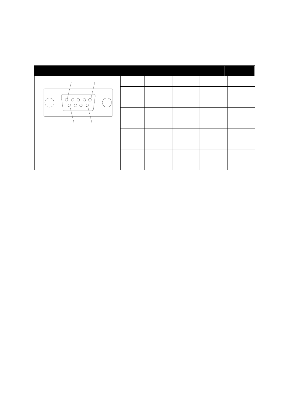
The analogCUE has (32) outputs 0 - 10 V. All outputs are connected on (4) DB-9-female connectors
marked OUT 1 - 8, OUT 9 - 16, OUT 17 - 24 and OUT 18 - 32. For details see table below.
OUTPUT 1 - 32, (4) DB-9-female connectors
OUT 1 - 8
OUT 9 - 16
OUT 17 - 24
OUT 18 - 32
Pin 1
Output 1
Output 9
Output 17
Output 25
Pin 2
Output 2
Output 10
Output 18
Output 26
Pin 3
Output 3
Output 11
Output 19
Output 27
Pin 4
Output 4
Output 12
Output 20
Output 28
Pin 5
Output 5
Output 13
Output 21
Output 29
Pin 6
Output 6
Output 14
Output 22
Output 30
Pin 7
Output 7
Output 15
Output 23
Output 31
Pin 8
Output 8
Output 16
Output 24
Output 32
1
5
6
9
Pin 9
Ground Ground Ground Ground
Parameters of the analog output
• Range of the output voltage
0 - 10 V
• Stepping regulation (LSB)
39 mV
• Min. set-up precision
± 0.08 V (± 2 LSB)
• Min. overrun period (LSB - MSB)
0.5 ms
•
Output
impedance
1
Ω
When connecting with another device (e.g. dimmer) it is essential to see to a perfect interconnection
with earth. The output voltages generated by the analogCUE are mutually related to the reference
level (ground of the interfaces analogCUE) on pin 9 of the output connectors.