Front panel description, Overview, Indicators – CUE smartCUE User Manual
Page 17: Buttons
User Manual Interfaces
www.cuesystem.com
Page 17 of 44
5.4. Front Panel Description ..............................................
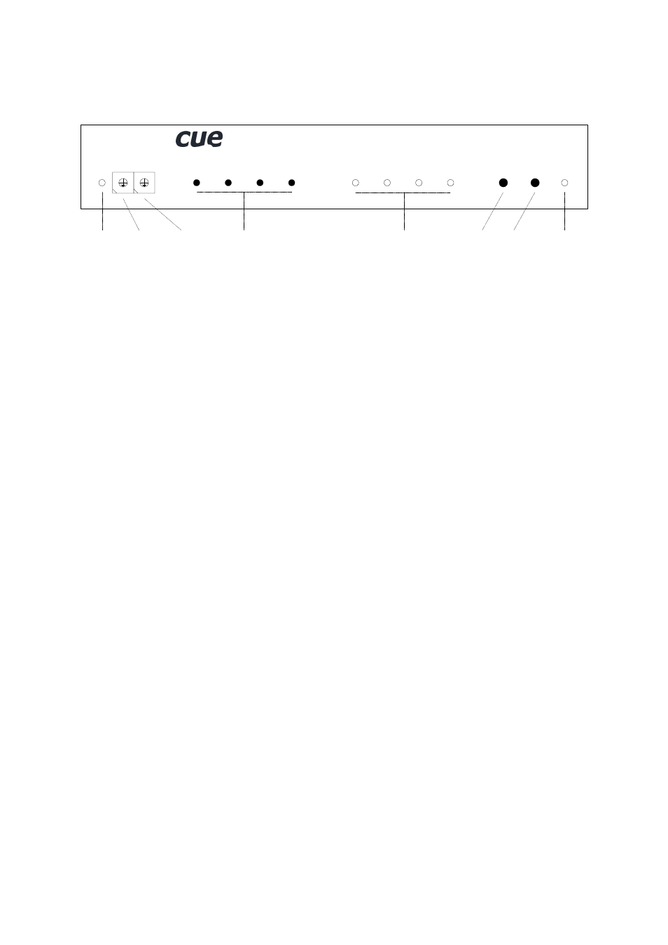
5.4.1. Overview
0
5
4
3
1
2
6
7
8
9
TE
ST
RE
SE
T
AD
DR
ES
S
DA
TA
O
.K
.
smartCUE
Data
Indicator
Address
Selector
Test
Button
Reset
Button
Power Supply
Indicator
Function
Buttons
0
5
4
3
1
2
6
7
8
9
BA
NK
Bank
Selector
F3
F4
F2
F1
A
B
C
D
Function
Indicators
5.4.2. Indicators
DATA O.K.
This LED diode is blinking if the interface received correctly the data coming from the CUEring. This
LED blinks OK by Morse after power on, if auto-diagnostic runs correctly.
A, B, C, D
The LED diodes are signaling activity on IR / serial ports. When transmitting IR code, LED indicator
DATA O.K. and respective A, B, C, D indicators are on. If IR code requested from programming is not
in the EPROM, error is indicated by indicator A, B, C or D flashing. Flashing is also stopped if next IR
signal is transmitted OK. When error occurs on serial channel the appropriate LED will start to blink
regularly to make the error indication. This indication will not stop until reset or until the appropriate
button F1 - F4 is pressed or new command was successfully finished.
POWER
Power diode indicates that the interface is powered up.
5.4.3. Buttons
TEST
This button serves for switching over to the testing mode. A detailed description of the testing you can
find in the chapter Diagnostic.
RESET
This button serves for resetting of the interface. During normal operation it is not being used, it solely
serves for testing purposes.
F1, F2, F3, F4
Buttons F1, F2, F3 and F4 serve for reset of errors signalizing for channel 1, 2, 3, 4.