Front panel description, Overview, Indicators – CUE smartCUE User Manual
Page 23: Buttons
User Manual Interfaces
www.cuesystem.com
Page 23 of 44
6.3. Front Panel Description ..............................................
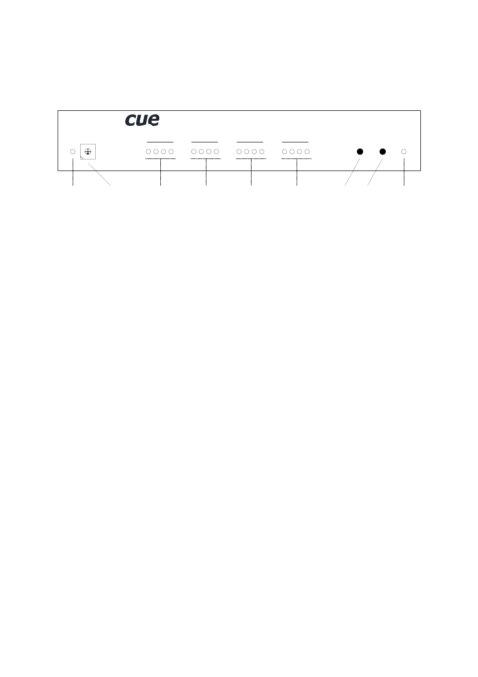
6.3.1. Overview
0
5
4
3
1
2
6
7
8
9
A
B
C
D
A
B
C
D
A
B
C
D
A
B
C
D
OU
T
1
OU
T
2
OU
T
3
OU
T
4
TE
ST
RE
SE
T
AD
DR
ES
S
DA
TA
O
.K
.
soundCUE
Data
Indicator
Address
Selector
Test
Button
Reset
Button
Output 1
Indicators
Output 4
Indicators
Output 3
Indicators
Output 2
Indicators
Power Supply
Indicator
6.3.2. Indicators
DATA O.K.
This LED diode is blinking if the interface received correctly the data coming from the CUEring. This
LED blinks OK by Morse after power on, if auto-diagnostic runs correctly.
OUT 1 to 4
(4) LEDs for each output indicate selected input. Indication is as described bellow, { means LED no
lights, z means LED lights
{zz{
Microphone input selected
z{{{
Line input A selected
{z{{
Line input B selected
{{z{
Line input C selected
{{{z
Line input D selected
POWER
Power diode indicates that the interface is powered up.
6.3.3. Buttons
TEST
This button serves for switching over to the testing mode. A detailed description of the testing you can
find in the chapter Diagnostic.
RESET
This button serves for resetting of the interface. During normal operation it is not being used, it solely
serves for testing purposes.