CIRCUTOR TR16 Series User Manual
CIRCUTOR Measuring instruments
1. DESCRIPTION OF THE DEVICE
The
TR16-RS485 is a measurement device for up to sixteen direct current channels
and a voltage channel of up to 1000 V of direct voltage. The measurement of the
current is done by means of sixteen Hall effect transformers (transformer for mea-
suring direct current), with 25 A primary.
The device has 2 RS-485 communications ports. The first of these is used to
connect and transmit the information to the master by means of the Modbus/RTU
protocol. The second communications port, allows for setting up a multi-master type
of communications typology (see section 4.5. Connection diagram of the RS-485
slave and sub-slave connection bus), given the multitude of applications that can
be comprised by a large number of
TR16-RS485 analysers. The communications
parameters can be configured by using the selectors located on the front panel of
the device.
Moreover, this device is equipped with 3 (logical) digital inputs, for detecting the
status of digital signals, coming from the device's surroundings and the information
of which is also available via RS-485 communication. Apart from the digital inputs,
the device is equipped with an analogue input with a 0...20 mA range and an input
for a configurable Pt100 or Pt1000 probe.
2. PRELIMINARY CONSIDERATIONS
2.1 Verifications on receiving
Upon receiving the instrument verify the compliance of the following points:
• The device corresponds to the specifications of your order.
• Verify that the device has not been damaged in transit
2.2 Safety precautions
For the safe use of the device, it is essential that the people who install or handle it
follow the usual safety measures, as well as the warnings documented in the said
instructions manual.
The
TR16-RS485 device has specifically been designed to be installed inside an
electric or enclosed cabinet, fastened to a DIN rail. Under no circumstances may
the device be installed or integrated into a place where it is in direct contact with
people. The
TR16-RS485 is fitted with a blinking red LED light (CPU), which warns
that it is running, and therefore warns of the presence of voltage and current in the
electronic circuit. Even though the LED light is not on, this does not free the user of
verifying that the device is disconnected from all power sources.
3. INSTALLATION AND START-UP
This manual contains information and warnings that the user must adhere to in
order to guarantee the safe operation of the device, and maintain it in a good state
with regards to safety. In its usual operation it should not be used until it has been
mounted in its final location in the electric cabinet.
IMPORTANT!
If the equipment is used in a manner not specified by the manu-
facturer,
the device's protection may be compromised.
When it is probable that the device may have lost its safety protection (for example,
if visible damage can be seen), the device must be disconnected from the power
supply. In this case, contact the qualified technical service or otherwise contact our
Technical assistance Service (see section 7. TECHNICAL ASSISTANCE SERVI-
CE).
3.1 Equipment installation
The installation of the device is of the DIN rail type; it has a surface of 9 DIN modu-
les (160 mm), and a height of 58 mm. All the connections remain accommodated
inside the electric cabinet.
Take into account that with the equipment connected, the terminals and the opening
of the covers or the elimination of elements, may give access to parts that it is hazar-
dous to touch. The equipment must not be used or powered up until its installation
has been fully completed.
IMPORTANT!
DC power supply of TR16 must be protected by fuses, circuit-breaker or any
other devices providing overcurrent protection. This devices must be set accor-
ding to the DC installation power.
The equipment must be connected to a fuse-protected power circuit, in accordance
with its power supply range and consumption. In turn, the power supply circuit must
be fitted with a circuit breaker switch or an equivalent device, in order to be able to
disconnect the equipment from the power supply grid. The power supply circuit must
be connected using a cable with a minimum section of 1 mm
2
.
3.2 Power supply of the equipment
The device has two auxiliary power supply inputs; one for alternating current and the
other for direct current. Under no circumstances may the user connect both power
supply inputs simultaneously.
Power Supply
AC
DC
Nominal voltage
230 V ac ≈
24 V dc =
Power supply tolerance
± 20%
± 10%
Frequency
50 Hz
-
Equipment consumption without transformers
2 V·A
2 W
Equipment consumption with 16 sensors (without load)
14 V·A
8 W
Equipment consumption with 16 sensors (with current load) 24 V·A
14 W
Operating conditions
Operating temperature
-10 ... 65 ºC
Relative humidity
5...95 RH without condensation
Maximum operating height
2,000 metres
Protection
IP20
TR16-RS485 accuracy
Current measurement (without current sensor)
± 0.5 %
Minimum current threshold
350 mA
Voltage measurement
± 1 %
Temperature
± 3 ºC (-30 ... 80 ºC)
Temperature input accuracy
Pt100 / Pt1000 temperature probe
± 3 ºC
Analogue input accuracy
Input accuracy 0...20 mA
± 0.5 %
Input impedance
165 Ω
Resolution in dots
1024 dots
Converter resolution
10 bits
Safety
Category III – 300 V AC (EN61010)
Double-insulated electric shock protection class II
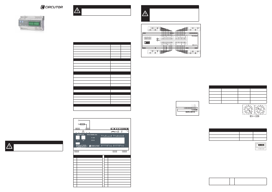
4. CONNECTIONS
4.1 Description of the connection terminals
Vd2
Vd1
Vd(1000Vdc)
A(+) S(GND) B(-)
COM1 RS485/S
A(+) S(GND) B(-)
COM2 RS485/M
AC POWER
SUPPLY 230 Vac
AC POWER
SUPPLY 24 Vdc
Pt 100/1000
ANALOG DIGITAL
|1 |2 |3 COM
1 2
22 23 24
3
4 5 6
7 8 9 10 1112
16 17 18
19 20 21
13 14 15
1A / 250V
Description
Description
1
Power supply 230 Vac
(phase or neutral)
13 Digital input 2
2
Not used
14 Digital input 3
3
Power supply 230 Vac
(phase or neutral)
15 Common digital inputs
4
Power supply 24 Vdc (positive)
16 Direct voltage (positive)
5
Not used
17 Not used
6
Power supply 24 Vdc (negative)
18 Direct voltage (negative)
7
Pt100 / Pt1000 probe input
19 Slave RS485 port (A – positive)
8
Pt100 / Pt1000 probe input
20 Slave RS485 port (S – GND)
9
Pt100 / Pt1000 probe input
21 Slave RS485 port (B – negative)
10 Analogue input 0...20 mA (positive)
22 Master RS485 port (A – positive)
11 Analogue input 0...20 mA (negative)
23 Master RS485 port (S – GND)
12 Digital input 1
24 Master RS485 port (B – negative)
IMPORTANT!
If a transformer not specified by the manufacturer is connected,
or it is connected to a different primary current than that specified
in this manual, the current measurement will be incorrect and the
device's protection may be compromised.
If no probe is connected to the device, you must make a bridge
between the three terminals meant for the probe. (7, 8, 9).
S10
S12
S
11
S9
4.2 Connection diagram of the current transformers
The
TR16-RS485 is a device designed to measure up to 16 direct current lines
simultaneously. The device is equipped with 16 inputs for Hall effect transformers,
with which one can measure up to 25 A per direct current channel.
Detailed connection diagram of the M/TR transformers
For connecting the M/TR-25A to the
TR16-RS485, device, the use of a screened
cable is recommended, the mesh of which must solely be connected to the GND
connector on the device
.
Optionally, up to a maximum of four M/TR-25Ax4 modules (16 channels) can be con-
nected to the
TR16-RS485 device. After initialising, the equipment performs a scan
of all the inputs of the transformer modules, disabling the unused, and consequently
not physically connected inputs, by software. In the event that a new four transformer
M/TR module is subsequently connected, the user must reset the device's power
supply, for the four new current measurement transformers to be recognised.
4.3 Connection diagram of the digital inputs
The
TR16-RS485 device has three voltage-free
inputs and a voltage of 24 V DC on the com-
mon one for detecting the logical status of the
external pickups. On a real-time basis it detects
the status of the inputs (open contact or closed
contact), and transmits this information through
the RS-485 communications bus.
The use and cabling of the said inputs is entirely optional and its implementation
does not affect the operation of the rest of the assembly.
4.4 Connection diagram of the conventional RS-485 communications
bus
The
TR16-RS485 has an RS-485 communications port for real-time connection
with a master PLC or SCADA industrial control type communications system. The
communication must be made using a twisted-pair mesh-screened communications
cable, with a three-core minimum. Between the master system and the last peri-
pheral, the systems allows for a maximum distance of 1,200 metres. A maximum
of 32 parallel-connected peripherals may be connected to the communication bus,
for each port used.
In any event, star-type installations must be avoided, as the communications bus
output of a peripheral must be chained to the input of the next and successive ones.
For installing these devices, it should be noted that there is no prior need of any type
of end-of-line resistor. SEE DIAGRAM A
4.5 Connection diagram of the RS-485 slave and sub-slave commu-
nications bus
The
TR16-RS485 has a second communications bus, which has the purpose of
being able to communicate with other
TR16-RS485s in a parallel manner (sub-
slave devices).
The nodes connected to the main bus, can simultaneously be connected to 15 new
devices. Therefore, at the main bus level, a maximum of 32 devices can be installed,
plus 15 sub-slave devices per installed node.
This communications typology results in the installation of 512 nodes on a single
communications network, without this fact penalising the pooling time of the main
communications bus.
The leading device connected to the main network, registers all the memory addres-
ses of the sub-slave devices connected to it, thus reducing the number of nodes to
be queried along the communications bus by the communications master, therefore
reducing the pooling time.
The typology and the connections setup is described in DIAGRAM B
5. CONFIGURATION
In that relating to the measurement of voltage or direct current, the device does not
require any special type of configuration, as the internal adjustment configuration
ranges come set from the factory.
5.1 Communications
The implemented communications protocol is of the MODBUS/RTU® type.
As shown in the connection diagrams, the
TR16-RS485 peripheral is connected to a
control system by means of the RS-485 bus. For this purpose, each of the devices
must be assigned a node number to identify them within the communications bus.
The front panel of the device is fitted with rotary switches and MINI-DIP switches
that allow the user to adjust the parameters of the different communications settings.
To integrate the device in the bus, only the node or peripheral number and the
transmission speed of the RS-485 bus need to be set, which must naturally be the
same as that of the communications master.
By default, the communication is set to 1 stop bit, Parity No and 8 bits in length
(8/N/1).
5.2 Setting the peripheral number.
The two rotary switches on the front panel of the device, are used to set the peri-
pheral number (node). As the device communicates in Modbus/RTU protocol, the
peripheral or station number may vary in the range 1 to 255 (FF in hexadecimal).
The node number is set in hexadecimal format; under no circumstances may this
be set in decimal format. See several examples of the conversion of decimal to
hexadecimal:
Decimal Node
Hexadecimal Node
Decimal Node
Hexadecimal Node
10
0A
80
50
15
0F
150
96
25
19
180
B4
50
32
200
C8
65
41
255
FF
For the hexadecimal node number, the first
digit is set with the left-hand switch and the
second with the right-hand switch. After the
device number has been set, it is not neces-
sary to reset the device.
5.3 Setting the transmission speed
The
TR16-RS485 has a module with four (MINI-DIP) switches, which allow the
transmission speed to be set using switches 1 and 2. See the following table:
Transmission speed
Switch 1
Switch 2
9,600 / 8 / N / 1
OFF
OFF
19,200 / 8 / N / 1
OFF
ON
38,400 / 8 / N / 1
ON
OFF
When a change is made to the transmission speed, it is not
necessary to reset the device. Nor when the node (peripheral)
number is changed.
5.4 Setting slave and sub-slave devices
Using switch number 3, the user can set the type of communications typology. The
device may be set as a conventional slave of a communications network, or otherwi-
se as a sub-slave within a multislave network.
5.4.1 Slave devices
In DIAGRAM A, the communications bus is of a conventional communications typo-
logy. In this type of typology the peripherals may be numbered from 1 to 255 (from
01 to FF in hexadecimal).
Position of Switch 3
Diagram A
OFF
The numbering of the node numbers
may vary between 1 and 255 (from
01 to FF in hexadecimal).
TR16-RS485-25A
Voltage and direct current multi-channel analyser
M98234101-03-15A