Earth cable connection, Current transformer (ct) connection – CIRCUTOR OPTIM P&P Series User Manual
Page 13
3.8.- EARTH CABLE CONNECTION
Connect the earth cable to the capacitor bank's earth terminal located on the operating panel
of the unit.
The earth cable cross-section will be selected in accordance with the admissible current limits
established in the LVR (ITC-BT-19 – Internal or receiver installations) for each type of cable and
their location.
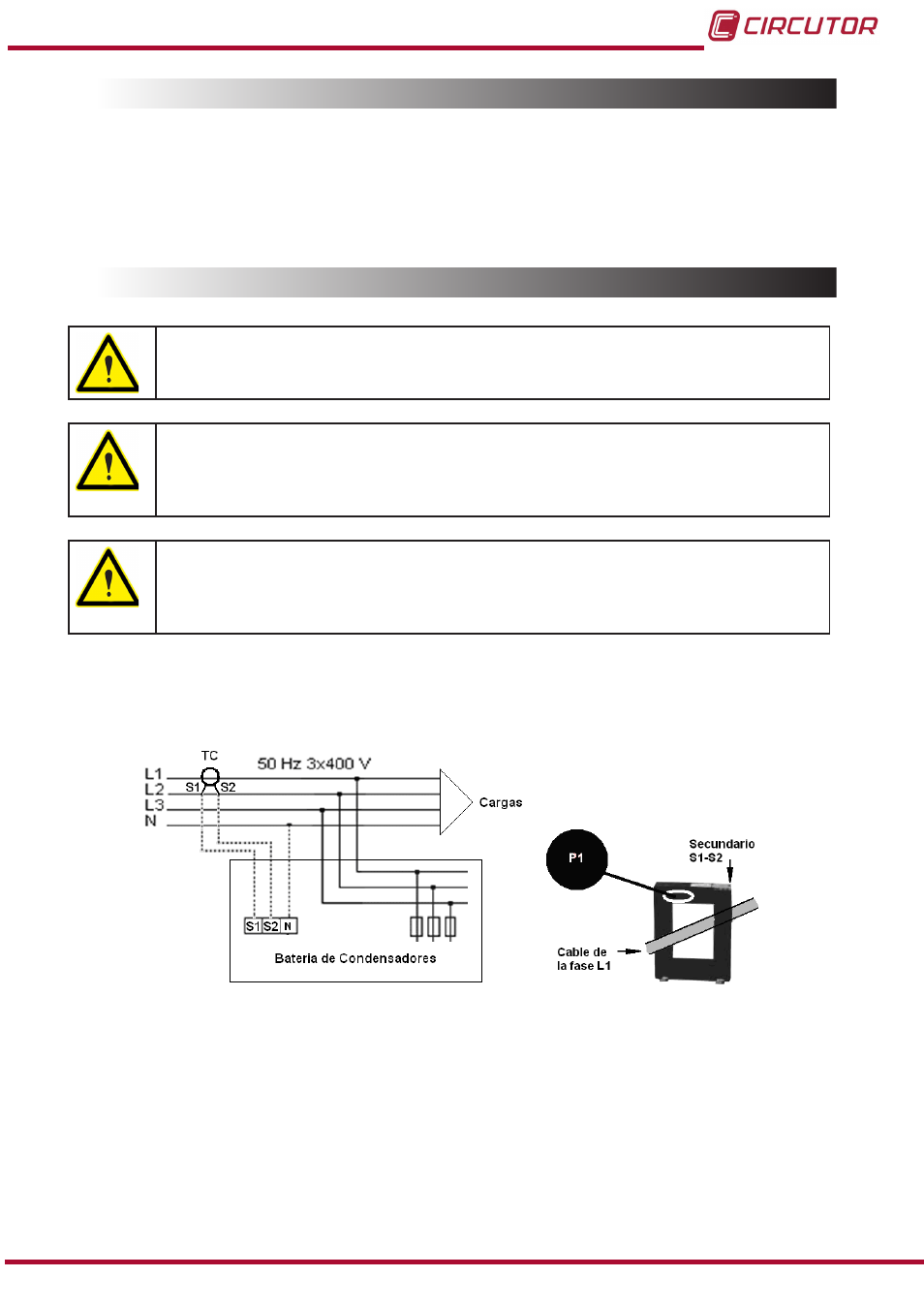
3.9.- CURRENT TRANSFORMER (CT) CONNECTION
A current transformer (CT) that is external to the capacitor bank must be
installed to measure the total load current plus that of the capacitor bank
The standard transformer must have a nominal output of 5 A at the secondary.
We recommend connecting the CT to phase L1 in the direction of the current flow
from P1 to P2 (see
) and connecting the secondary (terminals S1, S2) to
the terminals with the same name on the capacitor bank (see
)
Avoid current flow through the CT primary winding prior to connecting it to termi-
nals S1 S2 of the bank.
If the CT must be installed while the installation is under load, short-circuit S1 and
S2 while they are not connected to the capacitor bank.
The current value of the CT primary winding must be equal to or slightly greater than the size of
the mains switch of the installation. Therefore, the CT must be able to measure the maximum
current expected to be consumed by all the loads being compensated.
Figure 6: Installation of the external current transformer (CT).
The connection point of the CT for a capacitor bank that compensates an entire installation is
after the mains switch of the installation.
To prevent excessive attenuation of the signal, it is recommended that the minimum cross-sec-
tion of the secondary section winding cable (terminals S1, S2) is at least
2.5 mm
2
.
13
Instruction Manual
OPTIM P&P Series