Power net, There is no answer in broadcast frame – CIRCUTOR PowerNet Series User Manual
Page 2
______________________________________________________________________________
POWER NET
M98146001-03-11C
5
TECHNICAL FEATURES
Measured current
WG-35
50 / 100 / 250 (A)
WG-70
500 / 1000 (A)
Electrical features
Maximum voltage
720 V c.a
Isolation voltage
3.000 V c.a
Supply
L1-L2 :
400 V c.a. AC
Voltaje tolerance
-15 % / +10 %
Frequency
50…60 Hz
Consumption:
4,2 VA
Measure
300 V c.a AC (f-n)
Nominal voltage
520 V c.a. AC (f-f)
Frequency
45…65 Hz
Nominal current
(según transformador)
Permanent overload
1,2 In
Voltage circuit consumption
0,75 V·A
Mechanical and enviromental
Material
Plastic V0 self-extinguishing
Protection
IP 20
Dimensions (mm)
165 x 73 x 33
weight
0.220 kg
Work temperature
-10º…50 º C
Altitude
2.000 m
Humidity (without condensation) :
5%...95%
Accuracy
Voltage
0.5 % ± 2 digit
Current
0.5 % ± 2 digit
Power
1 % ± 2 digit
Measure condition without current transformers and direct voltage
Temperature
+ 5 … + 45 ºC
Power Factor
0,5…1
Measure range to end scale
10...100 %
Safety
Category III - 300 V c.a. / 520 c.a. EN-61010 Electric shock protection by double
isolation class II
Standards
IEC 664, UL 94, VDE 0414 IEC 664, VDE 0110, UL 94, IEC 801, IEC 348, IEC 571-
1, EN 61000-6-3, EN 61000-6-1, EN-61010-1
6
COMMUNICATIONS
The MEMORY MAP table shows the memory map addresses of each variable
that measures and calculates the analyzer and it’s code.
6.1
PERIPHERAL NUMBER AND BAUDRATE
It’s possible through a Modbus command to configure the device. The memory
locations that are changed are in the next table:
Modbus address
Modified variable
Valid range
3000, 3001
Device serial number
0 a 999999999
3002H
Peripheral number
1 a 255
3002L
Speed (baud rate)
0= 9600, 1= 19200
The Modbus command to send is (hex.):
Tx: 00100BB8000306NNNNNNNNPPVVCRC
Rx:
There is no answer in broadcast frame.
This command sets the peripherals number and the baud rate of communications
for devices connected in the same network that have the default peripheral
number. The command is sent to the peripheral number 0 (broadcast) to interpret
all devices, but only make the change the device that matches the serial number
is sent as parameter. The peripheral number and communications port speed be
set immediately, without requiring a reset of the device.
6.2
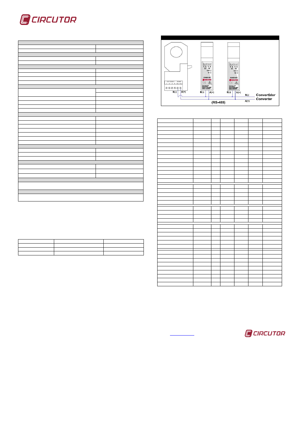
RS-485 LAYOUT
The picture shows how to connect a communication bus between multiple Power
Net. The converter can be RS-485 to RS-232 serial port or Ethernet depending
on the facility infrastructure. The standard RS-485 connection allows a maximum
of up to 32 peripherals in each bus.
CONEXION RS-485
6.3
MEMORY MAP
VARIABLE
SYMBOL COD
INST
MÁX
MÍN
UNITS
Phase voltage
V 1
1
00-01
60-61
C0-C1
V x10
Current
A 1
2
02-03
62-63
mA
Active Power
Kw 1
3
04-05
64-65
W
Reactive Power
Kvar 1
4
06-07
66-67
W
Power factor
PF 1
5
08-09
68-69
C8-C9
x100
Phase voltage
V 2
6
0A-0B
6A-6B
CA-CB
V x10
Current
A 2
7
0C-0D
6C-6D
mA
Active Power
Kw 2
8
0E-0F
6E-6F
W
Reactive Power
Kvar 2
9
10-11
70-71
W
Power factor
PF 2
10
12-13
72-73
D2-D3
x100
Phase voltage
V 3
11
14-15
74-75
D4-D5
V x10
Current
A 3
12
16-17
76-77
mA
Active Power
Kw 3
13
18-19
78-79
W
Reactive Power
Kvar 3
14
1A-1B
7A-7B
W
Power factor
PF 3
15
1C-1D
7C-7D
DC-DD
x100
Active Power III
Kw III
16
1E-1F
7E-7F
W
Inductive Power III
KvarL III
17
20-21
80-81
W
Capacitive Power III
KvarC III
18
22-23
82-83
W
Cos φ III
Cos φ III
19
24-25
84-85
E4-E5
x100
Power factor III
PFIII
20
26-27
86-87
E6-E7
x100
Frequency (L1)
Hz
21
28-29
88-89
E8-E9
Hz x10
Line voltage L1-L2
V12
22
2A-2B
8A-8B
EA-EB
V x10
Line voltage L2-L3
V23
23
2C-2D
8C-8D
EC-ED
V x10
Line voltage L3-L1
V31
24
2E-2F
8E-8F
EE-EF
V x10
%THD V 1
%THDV1
25
30-31
90-91
% x 10
%THD V 2
%THDV2
26
32-33
92-93
% x 10
%THD V 3
%THDV3
27
34-35
94-95
% x 10
%THD I 1
%THDI1
28
36-37
96-97
% x 10
%THD I 2
%THDI2
29
38-39
98-99
% x 10
%THD I 3
%THDI3
30
3A-3B
9A-9B
% x 10
Active Energy
Kwh III
31
3C-3D
Wh
Ind. Reactive Energy
KvarhL III
32
3E-3F
Wh
Cap. Reactive Energy
KvarhC III
33
40-41
Wh
Apparent Power III
KvaIII
34
42-43
A2-A3
W
Maximum Demand
Md(Pd)
35
44-45
A4-A5
W/VA/mA
Average current
I_AVG
36
46-47
A6-A7
mA
Neutral current
In
37
mA
Maximum Demand I2
Md(Pd)
42
52-53
B2-B3
mA
Maximum Demand I3
Md(Pd)
43
54-55
B4-B5
mA
7
ASSITANCE SERVICE
In case of operational doubt or equipment breakdown, call CIRCUTOR’s
Customer Service.
CIRCUTOR, S.A. – Customer Service
Vial Sant Jordi, s/n
08232 -Viladecavalls (Barcelona)
National phone
902 449 459
International phone: (+34) 93 745 29 00
fax – (+34) 93 745 29 14
E-mail :