CIRCUTOR CVM-1D Series User Manual
Page 2
CVM-1D
M98236001-03-14A
6.-
Modbus/RTU memory map
Parameters
Symbol
Var Instantaneous
Maximum
Minimum
Units
Parameters
Var
Symbol
Instantaneous Maximum Minimum
Units
Voltage
V
1
0000-0001
0032-0033
0044-0045
V x10
Partial Active Energy
14
kW·h
001A-001B
-
-
kW·h x100
Current
A
2
0002-0003
0034-0035
0046-0047
A x100
Partial Inductive Reactive Energy
15
kvarL·h
001C-001D
-
-
kvarL·h x100
Active Power
kW
3
0004-0005
0036-0037
0048-0049
± kW x100
Partial Capacitive Reactive Energy
16
kvarC·h
001E-001F
-
-
kvarC·h x100
Reactive Power (L/C)
kvar
4
0006-0007
0038-0039
004A-004B
± kvar x100
Partial Reactive Energy (L/C)
17
kvar·h
0020-0021
-
-
kvar··h x100
Inductive Reactive Power
kvarL
5
0008-0009
003A-003B
004C-004D
± kvarL x100
FOUR QUADRANTS MEASUREMENT
Capacitive Inductive Power
kvarC
6
000A-000B
003C-003D
004E-004F
± kvarC x100
Generated Active Energy
18
kW·h
0022-0023
-
-
kW·h x100
Apparent power
kVA
7
000C-000D
003E-003F
0050-0051
± kVA x100
Generated Inductive Reactive Energy
19
kvarL·h
0024-0025
-
-
kvarL·h x100
Power Factor
PF
8
000E-000F
0040-0041
0052-0053
PF
Generated Capacitive Reactive Energy
20
kvarC·h
0026-0027
-
-
kvarC·h x100
Maximum Demand
kW / A
9
0010-0011
0042-0043
0054-0055
kW / A x100
Generated Total Reactive Energy (L/C)
21
kvar·h
0028-0029
-
-
kvar·h x100
Active energy
kW·h
10
0012-0013
-
-
kW·h x100
Partial Generated Active Energy
22
kW·h
002A-002B
-
-
kW·h x100
Inductive Reactive Energy
kvarL·h
11
0014-0015
-
-
kvarL·h x100
Partial Generated Inductive Reactive Energy
23
kvarL·h
002C-002D
-
-
kvarL·h x100
Capacitive Reactive Energy
kvarC·h
12
0016-0017
-
-
kvarC·h x100
Generated Capacitive Reactive Energy
24
kvarC·h
002E-002F
-
-
kvarC·h x100
Reactive Energy (L/C)
kvar·h
13
0018-0019
-
-
kvar·h x100
Partial Generated Total Reactive Energy (L/C)
25
kvar·h
0030-0031
-
-
kvar·h x100
7.-
CVM-1D communication
One or several -CVM-1D analyzers can be connected to a controller or PLC. Using this system you can operate each of the analyzers as usual as well as centralize the data in a single
location. CVM-1D incorporates an RS-485 type communications output. If more than one analyzer is connected to an RS-485 serial bus, each of them must be assigned a peripheral
number or address so that the communications master can send the queries regarding the different measured or calculated records to those addresses.the RS-485 connection is carried out
via the shielded twisted pair communication cable, with a minimum of two wires and with a maximum distance between the communications master and the last unit of 1,200 metros. The
device uses an RS-485 communications line that can support a maximum of 32 units in series per bus.
The CVM-1D type power analyzer communicates via a Modbus/RTU© protocol (Question / answer polling).
8.-
Technical specifications
Supply specifications :
- Single-phase :
- Frequency:
- Maximum consumption :
88…276 V
c.a
50 / 60 Hz
2 VA
Metering circuit:
- Nominal voltage / Tolerance:
- Nominal voltage / MID Tolerance:
- Frequency :
- MID frequency:
- Nominal current/minimum/maximum:
- Start current (Ist):
- Reference current (Iref):
- Transition current (Itr):
110…230 V
c.a
/ ±20 %
230 V
c.a
/ ±20 %
50 / 60Hz
50Hz
5 A / 250 mA / 32 A
20 mA
5 A
500 mA
Mechanical specifications:
- Case material :
- Protection :
Fitted unit (front panel) :
Fitted MID unit (front panel) :
Non-fitted unit (front panel):
- Maximum Dimensions (mm) :
- Weight :
Selft-extinguish UL94-V0 plastic
IP31
IP51
IP20
85.5 x 64.2 x 18 mm (1 DIN rail module)
150 g
Output transistor specifications
- Typo:
opto-isolated transistor (open
collector)
- Maximum operating voltage:
- Maximum operating current:
- Maximum frequency:
- Pulse width:
NPN
42 V
c.c.
50 mA
1000 imp / kW·h
40…200ms (configurable)
Environmental specifications:
- Working temperature:
- Storage temperature:
- Humidity:
- Maximum altitude:
-5...+45 ºC
-25...+70 ºC
5…95% non condensing
2000m
Safety:
CATIII-300 EN61010-1:2010 EN61010-2-030:2011. Double insulation. Pollution degree II.
Means for disconnecting the power from the device must be provided in the installation.
Wire conductor are must be choosen depending on current to flow acroos the device.
Minimum recommended wire is 1mm
2
Standards :
EN 50470-1, EN50470-3, EN62053-21, EN62053-23, EN61010-1:2010,
EN 61000-6-4, EN 55022
Energy meter: Class B EN50470-3 Active Energy, Class 2 EN62053-23 Reactive
Energy.
Accuracy:
- Voltage :
- Current :
- Power / Energy :
Sensors :
- Voltage :
- Current :
Power factor :
Measurement range:
0.5 % ± 1 digit
0.5 % ± 1 digit
1 % ± 1 digit
Direct. Impedance 1M
Direct (shunt <0,5 m
)
0.5...1
0.5...120% FS
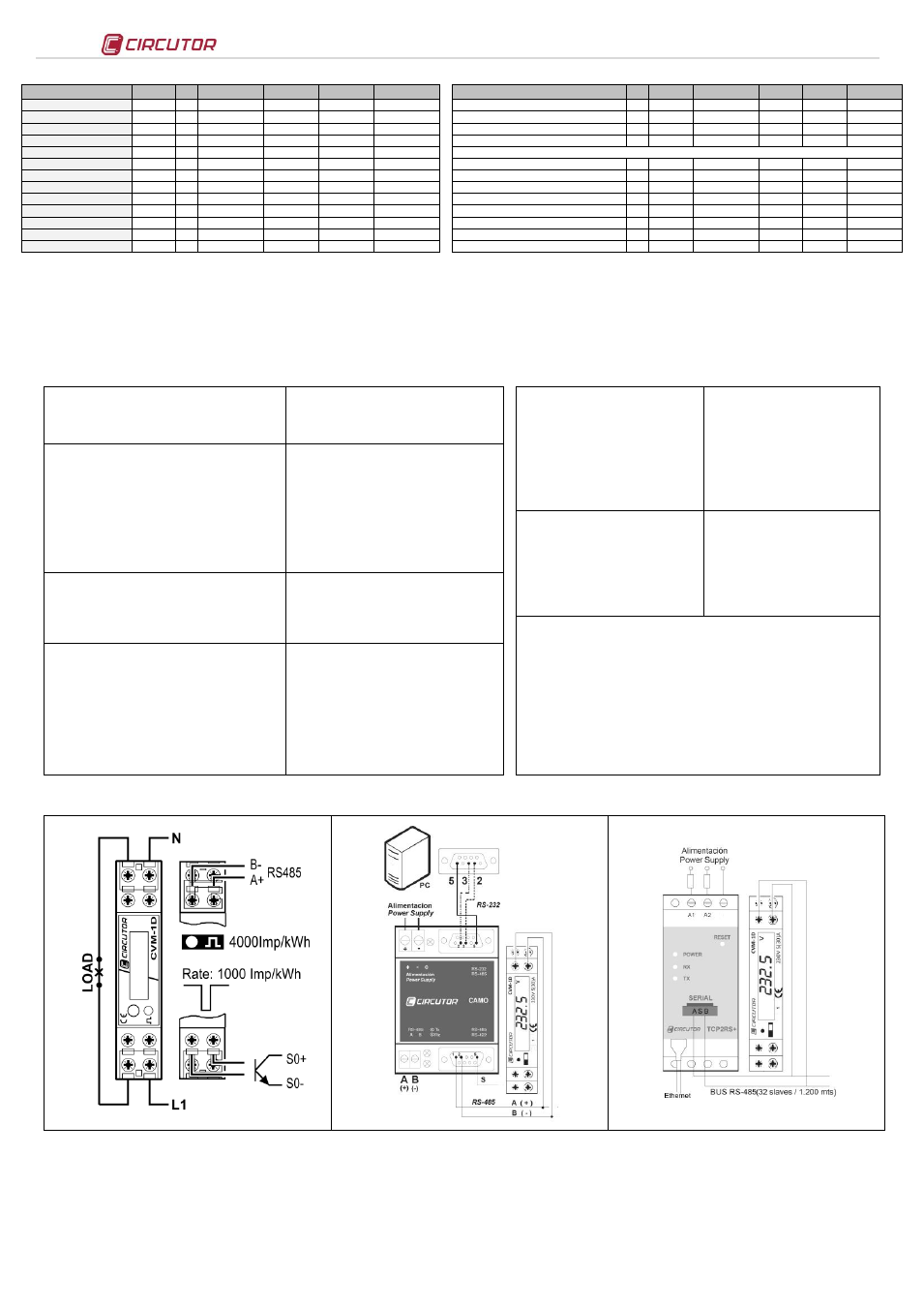
9.-
Connections
Single-phase connection system
RS-485 communications
10.- Technical Service
If you have any doubts about the operation of the unit or suspect any malfunction, contact our service staff at CIRCUTOR, SA
CIRCUTOR, SA - Technical Assistance Service
Vial Sant Jordi, s/n
08232
– Viladecavalls (Barcelona),Spain
Tel: 902 449 459SPAIN
Tel: (+34) 93 745 29 00 (outside of Spain)
email: