Casella CEL Sensus data logger unit User Manual
Page 26
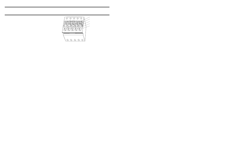
The pin connections for the
RS 232 Command - Spring terminal
connector are as follows.
Pin
Assignment
1
Ground
2
Transmit data (out)
3
Receive data (out)
4
DTR (out) (linked internally to 7)
5
CTS (in)
6.2
Sleep Mode
When enabled, the logger will conserve power by switching off the RS 232
interface circuitry after a period of inactivity. While in this state the logger is
still able to detect the arrival of characters over the command interface and
when the first character arrives, the logger will waken and switch on the RS
232 interface again.
However this does mean that the logger may not
interpret the first character correctly.
To wake and communicate with the Sensus Logger reliably, an
escape (ASCII code 0x1b) character should be sent before sending any
commands.
6.3
RS 232 Instrument
A second RS 232 interface is also located on the right hand end of the logger
case (Figure 15), marked RS232 Inst. It has a 6-pin mini DIN type
connector.
The pin connections for the RS 232 Inst connector are as follows.
Pin
Assignment
1
Ground
3
Receive data (in)
4
Transmit data (out)
This port is intended to allow data to be collected from equipment that has an
RS 232 output. The Sensus Logger is shipped from Casella CEL with the
instrument interface set to the following parameters.
Default parameters - Instrument interface
Baud rate
9600
Data bits
8
Parity
None
Stop bits
1
Handshake
None
Commuications
Figure 18: RS 232 connector
01080
Pin 1
Pin 2
Pin 3
Pin 4
Pin 5
Page 26 of 44
SENSUS Digital Data Logger -
Users Handbook