Input connections, Figure 5: the connector cover label, Sensus digital data logger - users handbook – Casella CEL Sensus data logger unit User Manual
Page 20
5.
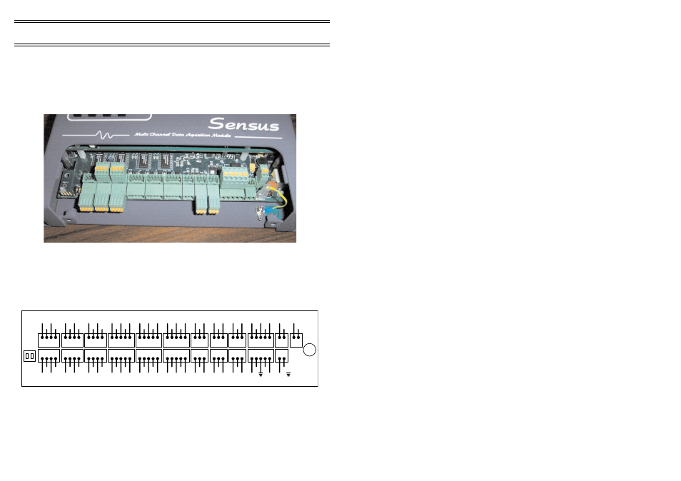
INPUT CONNECTIONS
Removing the connector cover plate gives access to the input connector
array. The connector array consists of 3, 4 and 5-way detachable connector
blocks to which sensor outputs are wired. The combination of spring-clamp
technology and plug-in modules allow for rapid and secure attachment of a
variety of sensors.
Channel numbering starts from the left-side, bottom-row and
alternates between the bottom and top row, from left to right. In addition the
pins of each connector are numbered from left to right.
A copy of this connector/pin assignment diagram is located on the
reverse of the connector cover plate for reference in the field.
Input Connections
Figure 4: The logger with cover removed
AN1
AN3
AN5
AN7
AN9
AN11
CNT1
CNT3
ALARMS
0V
0V
0V
0V
0V
0V
0V
0V
0V
-A
1
-A
3
-A
5
-A
7
-A
9
-A
11
C1
C3
AL
1
+A
1
+A
3
+A
5
+A
7
+A
9
+A
11
+V
+V
AL
2
I1
I3
I5
+Vsw
+Vsw
+Vsw
+Vsw
+Vsw
+Vsw
CHARGER
BATT
0V
0V
+CH
G
+CH
G
+CH
G
+CH
G
0V
0V
AN2
AN4
AN6
AN8
AN10
AN12
CNT2
CNT4
AN.OUT
0V
0V
0V
0V
0V
0V
0V
0V
VSS
-A
2
-A
4
-A
6
-A
8
-A
10
-A
12
C2
C4
A1
+A
2
+A
4
+A
6
+A
8
+A
10
+A
12
+V
+V
A2
I2
I4
I6
+Vsw
+Vsw
+Vsw
+Vsw
+Vsw
+Vsw
RS232
SOLAR
0V
-SP
TXD
+SP
-B
RXD
CTS
DTR
-A
RS485
01072
Figure 5: The connector cover label
Page 20 of 44
SENSUS Digital Data Logger -
Users Handbook