Casella CEL Sensus data logger unit User Manual
Page 22
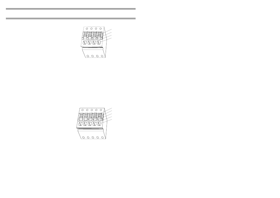
5.3
Analog 4-way Connectors
Logging
01073
0V
-Ax
+Ax
+Vsw
Figure 9: 4-way connector
01074
0V
-Ax
+Ax
+Vsw
ly
Figure 10: 5-way connector
The first 3 connectors of each row of
the connector array are intended
specifically for analog channels. They
have the following pin assignments.
4-way connectors - AN1 to AN6
0 V
Analog signal ground reference,
-Ax
Differential connection negative input,
+Ax
Differential connection positive input,
+Vsw
13.8 V switched supply for sensor
excitation. This excitation voltage is
common to all analog sensor connectors.
5.4
Analog 5-way Connectors
The next 3 connectors of each row of
the connector array are also intended
specifically for analog channels. They
have the following pin assignments:
5-way connectors - AN7 to AN12
0 V
Analog signal ground reference,
-Ax
Differential connection negative input,
+Ax
Differential connection positive input,
+Vsw
13.8 V switched supply for sensor
excitation. This excitation voltage is
common to all analog sensor connectors.
Iy
200 µA sensor excitation (this excitation
current can be switched between each of
these 5-way connectors).
Page 22 of 44
SENSUS Digital Data Logger -
Users Handbook