3 display elements and connections, Display elements and connections – AXING SKT 2-01 User Manual
Page 5
Common
SKT-2-01
© AXING AG – state of the art: July 2012 – Reserving change in design and type
Page 5
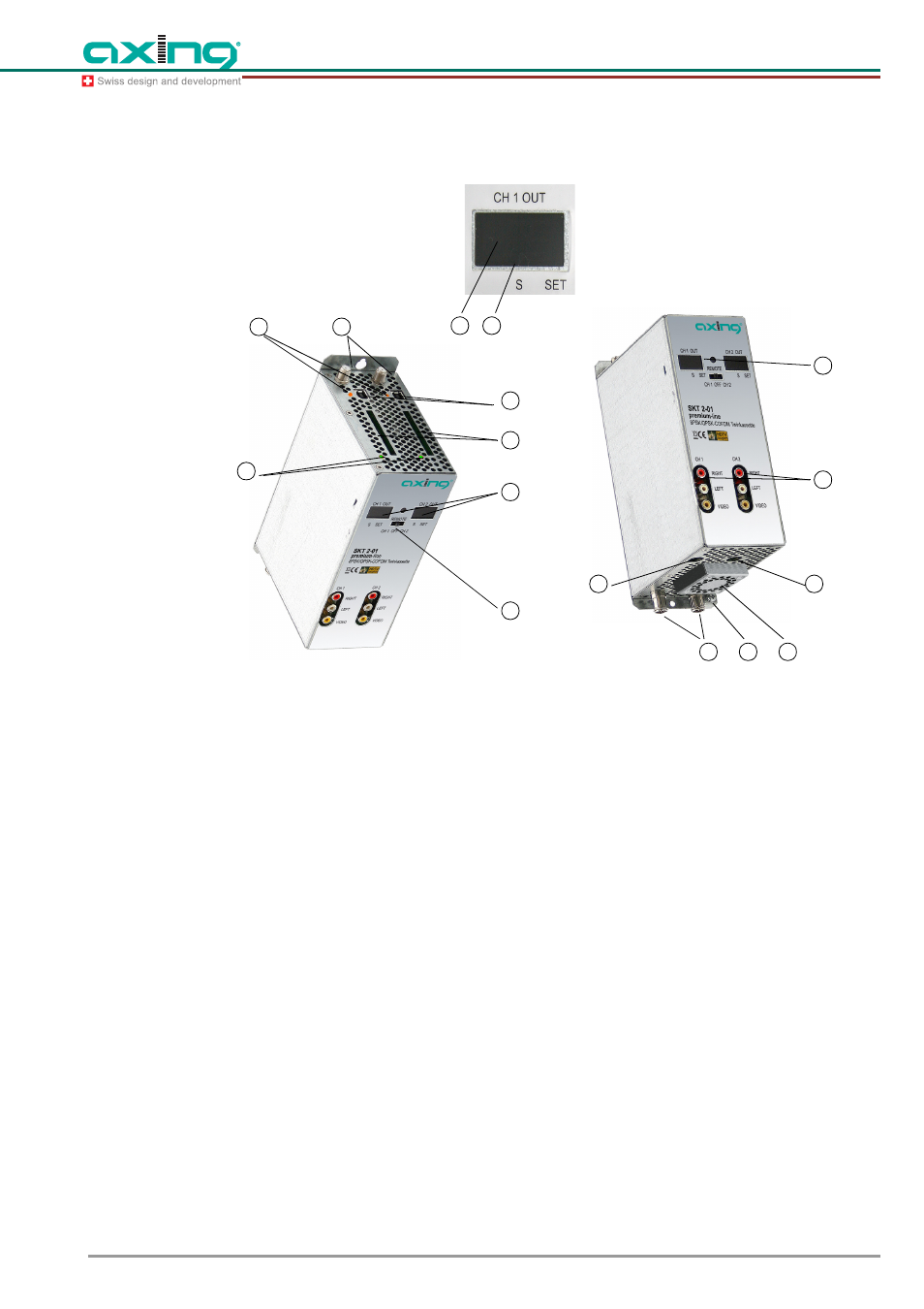
2.3 Display elements and connections
Fig. 2
Display elements and connections of the SKT 2-01
1
Programming selection switch (duct 1 - position left, duct 2 - position right). The switch must be in
central position after programming!
2
Display channel number
3
Display point special channels
4
LED display
Orange = MPEG data stream present, Off = MPEG data stream not present
5
LED display MPEG data stream
Red = too high Green = OK
6
SAT ZF input
7
USB input for software update
8
HF output and DC input (for installation in basic unit SKS x-x)
9
DC input/output (only for single operation)
10 DC input/output (for the power supply of three more SKT 2-01 twin modules in single operation and
not in SKS x-xx)
11 Audio/Video outputs (cinch) for monitor connection
12 Infrared receiver
13 CI ducts (for the fixture of CA modules)
Before installing CA modules, the power supply must be interrupted!
14 Grounding screw
15 Fan
7
8
9
10
11
12
13
2
1
3
4
2
6
14
02
5
15