3 dvb-t fec, 4 dvb-t bandwidth, 5 output level – AXING SKT 2-01 User Manual
Page 14: 6 fine tune, 7 exit modulator menu, 8 ci module recognized, 9 exit the configuration, Ci module recognized, Exit the configuration
Programming
SKT-2-01
© AXING AG – state of the art: July 2012 – Reserving change in design and type
Page 14
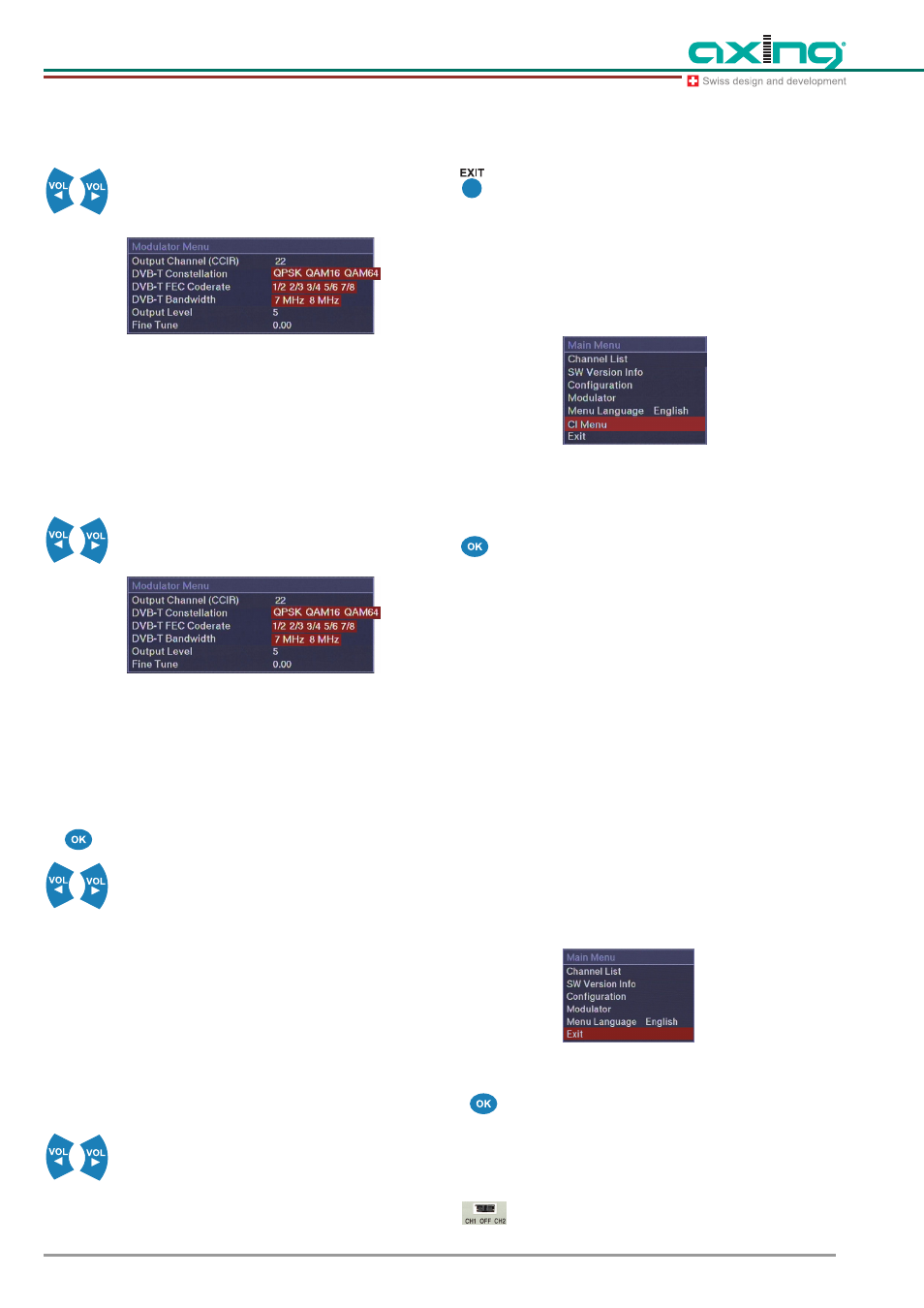
4.7.3 DVB-T FEC
The settings 1/2, 2/3, 3/4, 5/6 or 7/8 can be
selected by means of the VOL / VOL
keys.
Fig. 25
DVB-T FEC
The highest data stream is obtained with the 7/
8 setting and the highest data safety with the 1/
2 setting.
4.7.4 DVB-T bandwidth
Mit den VOL / VOL Tasten zwischen den
Einstellungen 7 MHz oder 8 MHz wählen.
Fig. 26
DVB-T bandwidth
At a bandwidth of 7 MHz the transmittable data
rate is reduced to approx. 1/8.
4.7.5 Output level
Select the menu item “Output level” and
confirm with OK.
Set the output level of the modulator in steps of
1dB by means of VOL / VOL .
20 corresponds to 105 dBµV. The maximum
level decrease is -20dB (setting = 0).
4.7.6 Fine tune
If the output channel does not correspond to
the CCIR pattern, the output frequency can be
changed using the Fine Tune adjustment.
Next to the channel number is displayed the
center frequency in brackets.
Change the center frequency if necessary by
up to 4 MHz in steps of 1 MHz upwards or
downwards.
4.7.7 Exit modulator menu
Press the EXIT key. The menu is closed and all
settings are saved.
4.8 CI module recognized
Before installing or deinstalling a CA modu-
le, disconnect the power supply!
Fig. 27
CI Menu
If a CA module is plugged in the duct, the "CI
Menu" submenu appears in the main menu.
Select the menu item “CI Menu” and confirm
with OK.
According to used CAM different settings can
be done.
It's also possible to make an enquiry about
smart card information.
The effects of the single settings in sub menus
are described from manufacturer of the CAM.
A module for 4 programs is able to decode 1 to
4 programs; if you try to decode a further
program, the SKT 2-01 produces a
malfunction!
The permission to decode encoded programs
in the head ends must be given by the
respective program provider.
4.9 Exit the configuration
Fig. 28
Exit the configuration
Select the menu item “Exit” and confirm with
OK.
After selecting the menu item “Exit”, the
programming is ended. All settings are saved.
The programming selection switch must be set
to center position.
!
!
!
!