Reestanding, Nstallation, Through the wall - direct installation – Dansons Group HCF300 User Manual
Page 15
Copyright 2004
15
Cheap Charlie
Owner’s Manual
Canadian Comfort Industries
www.dansons.com
Dansons Group Inc.
A
B
A
C
D
E
F
G
H
J
6”
1”
10”
6”
1”
10”
12”
F
REESTANDING
I
NSTALLATION
. . . continued
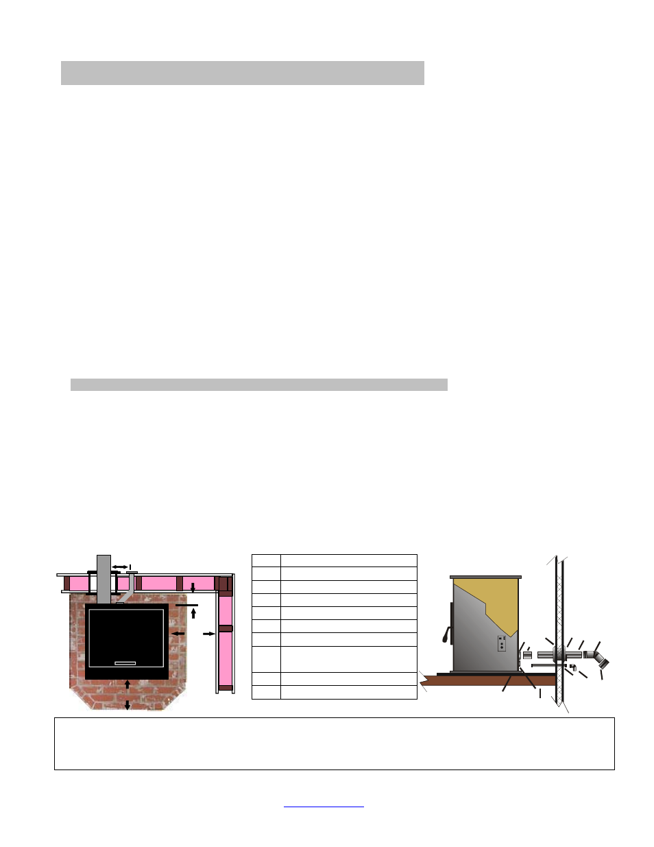
Figure 18
NOTE: Some horizontal, through the wall installations may require a Clean-Out Tee and a minimum 3’ vertical rise
of pipe outside the building to help draft the stove. This is required if a proper burn cannot be maintained, after the
stove has been tested and the airflow set. This is due to backpressure in the exhaust, caused by the airflow around
the house.
THROUGH THE WALL - DIRECT INSTALLATION.
(Figure 18)
1. Select the location for your stove, design the exhaust system and determine the brand and size of
"PL" vent to be used.
2. Position the floor pad. (C).
3. INSTALL VENT AT CLEARANCES SPECIFIED BY THE VENT MANUFACTURER
Following the "PL" vent manufacturer's specifications, mark and cut a hole through the wall to
accommodate the wall thimble, (A), and the outside air pipe, (B), if outside air is to be used.
• Install the wall thimble, (A). Be sure to run a bead of silicone around the outside edges of the
wall thimble to reduce drafts. Insert the proper size of "PL" vent, (D), through the wall thimble,
(A).
• Place your stove on the floor pad, (C), close to its final position. Leave room to connect the
"PL" vent to your stove. Place a bead of RTV silicone around the end of your stove's exhaust
pipe, (E). Connect the “PL” vent pipe adaptor (J) onto the stoves exhaust pipe.
• Connect the length of "PL" vent, (D), that is in the thimble, (A), onto the pipe adaptor (E).
Fasten together with at least three sheet metal screws (approx. ½” in length). Place a bead of
RTV silicone around the connection.
• Place your stove in its final position on the pad. Place another bead of RTV silicone around
the “PL” vent and the inside of the wall thimble, to stop cold air drafts.
Note: If 4" PL vent is required, use an increaser, (J), on the stove exhaust pipe.
4. On the outside of the building, place a 45 degree "PL" type elbow, (F), onto the end of the horizontal
"PL" vent, (D). Optionally, place a rodent screen cap, (G), (may be required in some locals), on the
end of the elbow, (F). Secure all connections using 3 sheet metal screws and run a bead of RTV
silicone around all connections. Also run a bead of RTV silicone around the “PL” vent pipe and the
outside of the wall thimble.
5. If outside air is used, install the outside air pipe, (B). Seal the outside air
pipe, (B), to your stove's outside air pipe, (I), with RTV silicone. Make
sure the outside air pipe fits over, (not inside), your stove's outside air
pipe. Install a wind shield (H). Run a bead of silicone around the inside
and outside walls, again to reduce cold drafts.
A
PL Wall Thimble
B
Outside Air Intake
C Hearth
Pad
D
PL Vent Length
E Stove
Exhaust
F
PL 45 deg elbow
G
PL Screened End Cap
H
Outside Air Intake Screen
Cap
I
Combustion Air Intake
J
PL Pipe Adaptor