Si3540, Introduction, Features – Applied Motion Si3540 User Manual
Page 4: Block diagram, Getting started
-3-
MOSFET
3 State
PWM
Power
Amplifier
motor phase A
motor phase B
110 or
220 VAC
INPUT1
INPUT2
INPUT3
INPUT4
CW JOG/IN5
CCW JOG/IN6
to PC/MMI
CW LIMIT/IN7
CCW LIMIT/IN8
OUT1
OUT2
OUT3
RS232
Optical
Isolation
Microstepping
Indexer
Sequencer
eeprom
Optical
Isolation
Internal
Power
Supply
power LED
fuse
Introduction
Thank you for selecting an Applied Motion Products motor control. We hope our
dedication to performance, quality and economy will make your motion control
project successful. If there’s anything we can do to improve our products or help
you use them better, please call or fax. We’d like to hear from you. Our phone
number is (800) 525-1609 or you can reach us by fax at (831) 761-6544.
Features
• Powerful, precise and efficient MOSFET driver providing up to 3.5 amps per phase
and microstepping to 50,800 steps per revolution.
• Reliable, efficient, low noise 40 VDC linear, toroidal power supply.
• Powerful, flexible, easy to use indexer.
• Connects by a simple cable to your PC for programming (cable included).
• Microsoft Windows
TM
-based software for easy setup and programming
• Eight inputs for interacting with the user and other equipment.
• Three outputs for coordinating external equipment.
• Accepts 110 or 220 volt AC power (factory preset for 110 volts).
• External trigger I/O is optically isolated, 5-24V, sinking or sourcing signals. PC/
MMI port is RS-232.
• Sturdy 2.25 x 7.8 x 5 inch metal chassis.
• Pluggable screw terminal connectors for motor, AC power and I/O signals.
• Optional man machine interface (MMI) allows operator to enter distances, speeds,
cycle counts and more.
• CE and TUV Compliant
Block Diagram
Si
TM
-4-
Getting Started
To use your Si3540 motor control, you will need the following:
✔ a power cable (line cord)
✔ a compatible step motor
✔ a small flat blade screwdriver for tightening the connectors - an Applied Motion
Products screwdriver suitable for this purpose is included with your drive.
✔ a personal computer running Windows 3.1, 95, 98 or NT with a 9 pin serial port
(486 or better with 8 MB ram recommended)
✔ the Si Programmer
TM
software that came with your Si3540
✔ the programming cable that came with your Si3540
✔ Si Programmer
TM
software manual
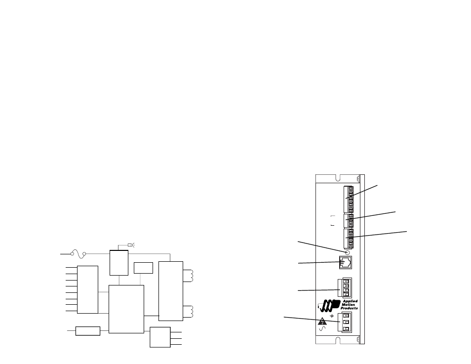
The sketch below shows where to find the important connection and adjustment
points. Please examine it now.
All Mating connectors included.
Always use the blue & white Applied
Motion screwdriver with the above
I/O connectors. Larger screwdrivers
may remove the plastic dimples that
prevent the screws from falling out.
POWER
MOTOR
AC
POWER
A+
A-
B+
B-
G
L
N
PC / MMI
INPUT 1
INPUT 2
INPUT 3
INPUT 4
IN 5 / JOG CW
IN 6 / JOG CCW
IN / JOG COM
IN / JOG COM
CCW -
CCW +
CW +
CW -
OUT 1 +
OUT 1 -
OUT 2 +
OUT 2 -
OUT 3 +
OUT 3 -
LIMITS
Si3540
Pr
ogrammable Step Motor Driver
AC power
connector
Motor connector
RS232 connector
pc
mmi
I/O connector
outputs 1-3
I/O connector
cw, ccw limits
I/O connector
inputs 1-4
jog cw, ccw
Power LED