Applied Motion 3535 User Manual
Page 6
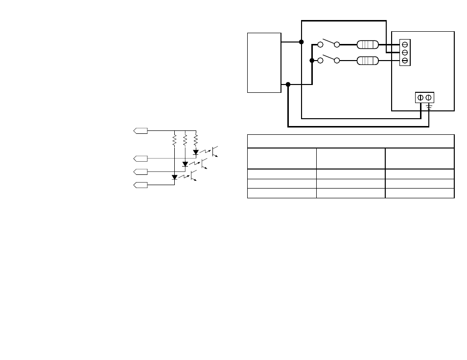
Supply
R
Supply
R
Supply
R
Voltage
Ohms
Voltage
Ohms
Voltage
Ohms
12
1200
21
3000
30
4700
15
1800
24
3600
33
5100
18
2400
27
4200
35
5600
Table I: External Dropping Resistors
Motor
Power
Supply
12-35
VDC
+
–
R
R
Run/Stop switch
(closed=run)
Direction
switch
3535 O
drive
STEP +5 DIR
12-35VDC
-11-
-6-
Connecting Logic
The 3535 and 3535 O contain optical isolation circuitry to prevent the electrical
noise inherent in switching amplifiers from interfering with your circuits. Optical
isolation is accomplished by powering the motor driver from a different supply than
your circuits. There is no electrical connection between the two: signal
communication is achieved by infrared light. When your circuit turns on or turns off
an infrared LED (built into the drive) it signals a logic state to the phototransistors
that are wired to the brains of the drive.
A schematic diagram of the input circuit is shown below.
You must supply 5 volts DC to activate the LEDs on the input side of the
optoisolators. The maximum current draw is 15 mA.
Your controlling logic must be capable of
sinking at least 5 mA to control each drive
input. Most CMOS and open collector TTL
devices are directly compatible with this drive.
Logic low, or 0, for a given input occurs when
that input is pulled to less than 0.8 volts DC.
In this state the LED is conducting current.
Logic high, or 1, occurs when the input is
greater then 4 volts or open.
STEP tells the driver when to move the motor one step. The drive steps on the
falling edge of the pulse. If the pulse is negative (low) the minimum width is 10
microseconds.
DIRECTION signals which way the motor should turn. See the step table on page 5
for details. The
DIRECTION signal should be changed at least 50 microseconds
before a step pulse is sent. If you change the state of the direction input
and send a step pulse at the same instant the motor may take a step in
the wrong direction.
ENABLE allows the user to turn off the current to the motor by setting this signal to
logic 0. The logic circuitry continues to operate, so the drive "remembers" the step
position even when the amplifiers are disabled. However, the motor may move
slightly when the current is removed depending on the exact motor and load
characteristics. If you have no need to disable the amplifiers, you don't
need to connect anything to the
ENABLE input.
DIR
STEP
+5V
Drive Input Circuit
1k
Ω
EN
1k
Ω
1k
Ω