Applied Motion 3535 User Manual
Page 3
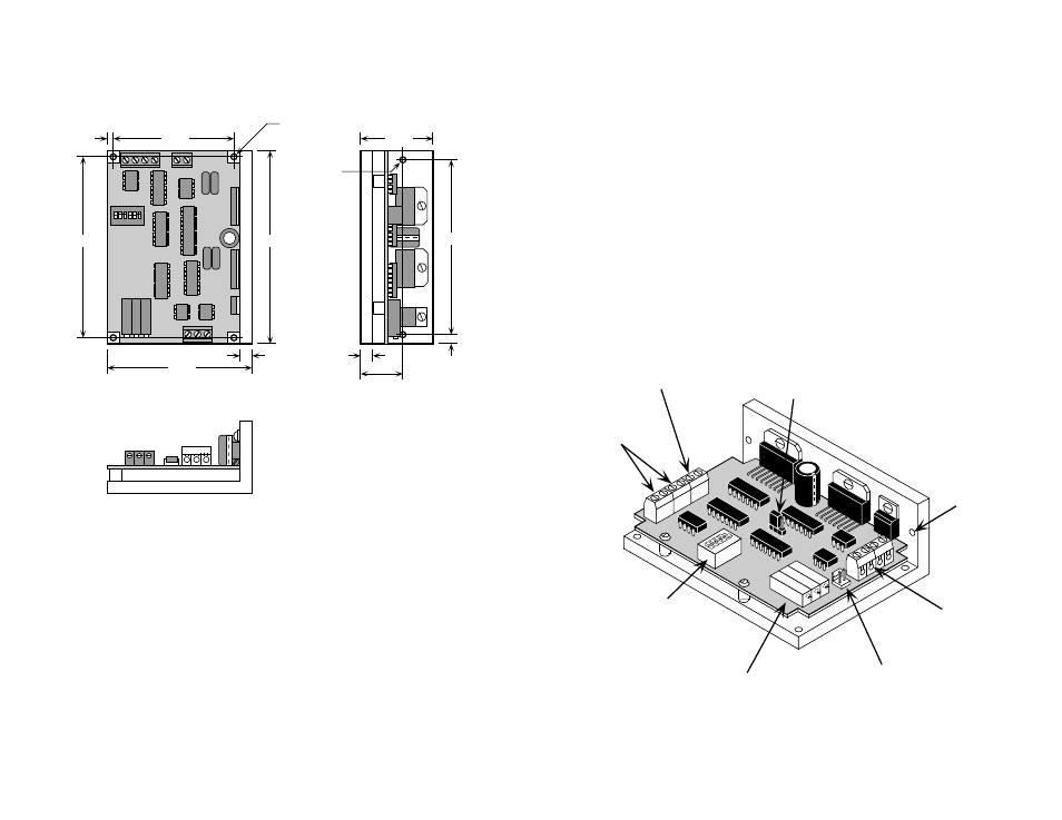
logic
connector
(
STEP, +5, DIR, EN
)
trimpots for adjusting
oscillator speed, accel and
decel rates
(3535 O only)
mounting
hole (1 of 6)
power
connector
motor
connector
switches for
selecting current &
full or half stepping
jumper for selecting
oscillator mode
(3535 O only)
-3-
-14-
Mechanical Outline
2.50"
3.75"
0.125"
3.00"
0.25"
4.00"
0.15"
4x Ø.125
3.70"
1.50"
0.25"
.875"
2x Ø.125
connector for external
speed control
(3535 O only)
Getting Started
To use your Applied Motion Products motor control, you will need the following:
• a 12-35 volt DC power supply for the motor. Please read the section entitled
Choosing a Power Supply for help in choosing the right power supply.
• +5 volts DC, 15mA to activate the optoisolation circuits (if you are using a 3535 O
and don't have 5V available, see page 8.)
• a source of step pulses capable of sinking at least 5 mA
• if your application calls for bidirectional rotation, you'll also need a direction
signal, capable of sinking 5 mA
• a compatible step motor
• a small flat blade screwdriver for tightening the connectors and adjusting the
oscillator
The sketch below shows where to find the important connection and adjustment
points. Please examine it now.