Nexen TCC Caliper 835121 User Manual
Page 7
4
FORM NO. L-20065-K-0110
ROTOR HUB
INSTALLATION continued
NOTE
The following sections are arranged by rotor
type. Verity that you are in the correct section
for your model.
1. Insert Key (Item 6) into shaft keyway and align Hub
(Item 1) keyway with shaft keyway and slide Hub
Assembly (Items 1-5) onto shaft.
NOTE
Allow 1/16" [16 mm] gap between Friction
Facings and Rotor Disc.
2. Tighten Set Screw (Item 7) to recommended torque
(See Table 2).
TABLE 2 Tightening Torques
TABLE 3 Q.D. Bushing Specifications
Description
TCB-10
TCB-14
TCB-20
Lock Nut
(Item 38)
32 ft-lbs
[43.0 Nm]
32 ft-lbs
[43.0 Nm]
32 ft-lbs
[43.0 Nm]
Set Screw
(Item 7)
23 ft-lbs
[30.9 Nm]
50 ft-lbs
[67.2 Nm]
166 ft-lbs
[223.1 Nm]
Jam Nut
(Item 10)
200 ft-lbs
[268.8 Nm]
200 ft-lbs
[268.8 Nm]
200 ft-lbs
[268.8 Nm]
Cap Screw
(Item 18)
27 ft-lbs
[36.4 Nm]
27 ft-lbs
[36.4 Nm]
27 ft-lbs
[36.4 Nm]
Set Screw
(Item 26)
23 ft-lbs
[30.9 Nm]
50 ft-lbs
[67.2 Nm]
166 ft-lbs
[223.1 Nm
Model
Bushing
Tightening Torque
TCB-10
JA
5 ft-lbs [6.4 Nm]
TCB-14
SK
15 ft-lbs [20.2 Nm]
TCB-20
J
135 ft-lbs [182.2 Nm]
Q.D. (TAPERED BORE) ROTOR HUB
CAUTION
Thoroughly inspect the tapered bore of hub
and tapered surfaces of the Q.D. bushing.
Remove any dirt, grease, or foreign material.
Do not use lubricants for this installation.
1. Assemble Q.D. bushing into hub, aligning untapped
holes of Q.D. bushing with tapered holes in hub.
2. Loosely insert pull-up bolts with Lock Washers into
Q.D. bushing and hub.
NOTE
Do not use lubricants or thread locking
compounds on these bolts.
3. With Key in shaft keyseat, slide the Hub Assembly
(Items 1-5) onto shaft.
4. Tighten pull-up bolts alternately and evenly to
recommended torque in Table 3.
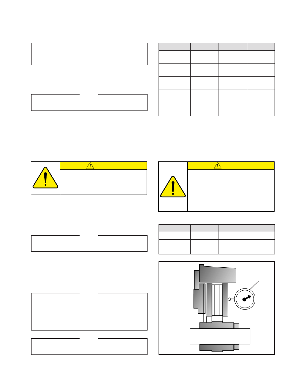
NOTE
Runout is minimized if a Dial Indicator is used
as the Q.D. bushing pull-up bolts are tightened.
Place the contact tip of Dial Indicator on the
machined surface of the Rotor to measure
runout. Runout must be less than 0.015'' [0.381
mm] TIR. (See Figure 6).
NOTE
Proceed with FRICTION FACING & CALIPER
installation.
CAUTION
The tightening force on the pull-up bolts
is multiplied several times by the wedging
action of the tapered surface. If extreme
tightening force is applied or if a lubricant
is used, bursting pressure will be created
in the splined hub. Follow recommended
tightening torque listed in Table 3.
Dial
Indicator
FIGURE 6