Nexen TCC Caliper 835121 User Manual
Page 6
3
FORM NO. L-20065-K-0110
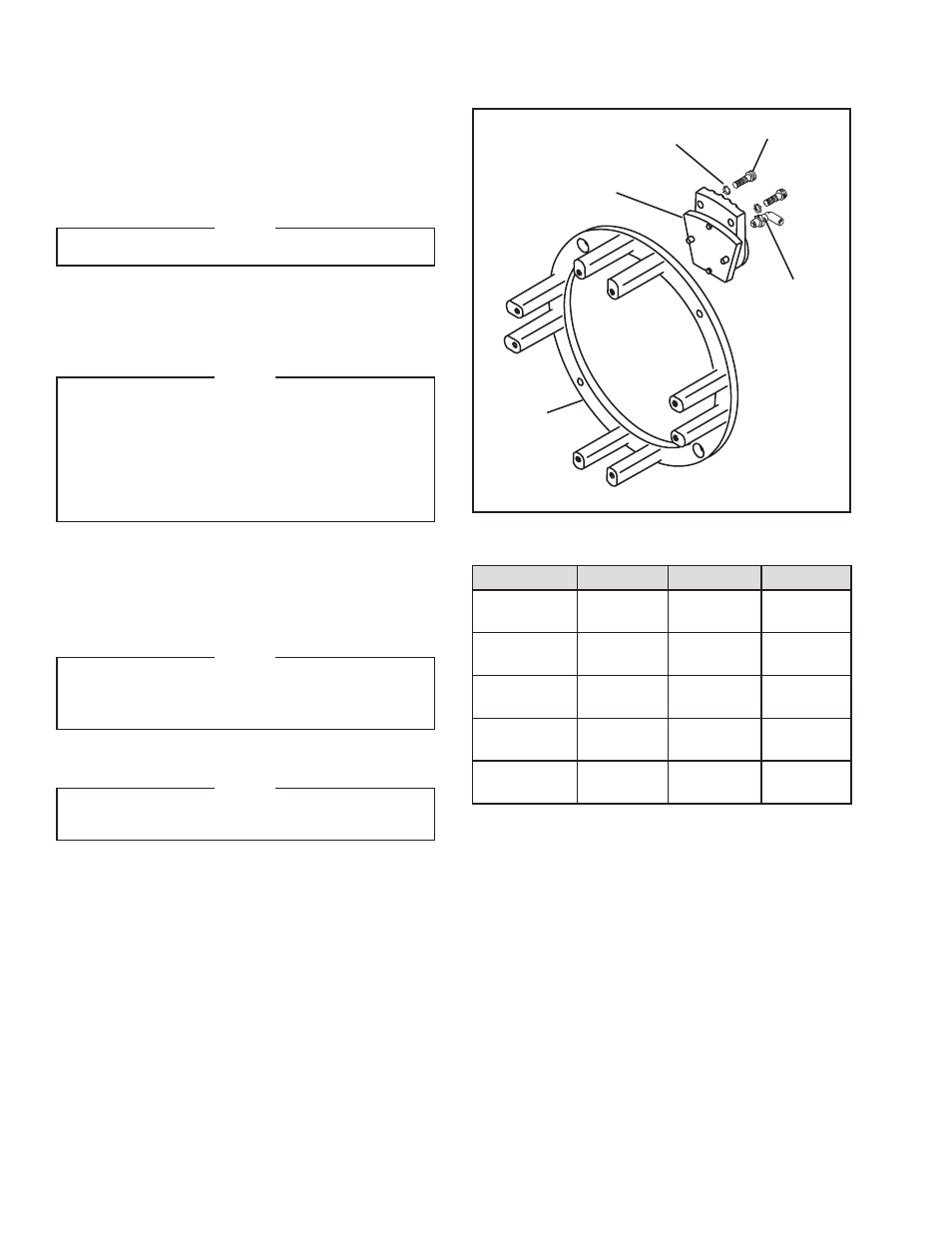
FIGURE 5
Housing
(Item 8)
Elbow Fitting
(Item 15)
or
Tee Fitting
(Item 16)
Caliper
Assembly Half
Cap Screws
(Item 18)
SHAFT MOUNTED TCB
REFER TO FIGURE 5.
1. Using Cap Screws (Item 36) and Lock Washers
(Item 37), fasten Torque Arm (Item 32) onto Housing
(Item 8).
NOTE
Use Cap Screws (Item 34) on TCB-20.
2. Using Cap Screws (Item 18) and Lock Washers
(Item 19), secure one-half of a Caliper Assembly
to flange side of Housing (Item 8). Tighten Cap
Screws to 7 ft-lbs [9.5 Nm] torque.
NOTE
Internal springs return the Caliper Piston to the
disengaged position to guarantee clearance
between Friction Facing and Rotor when no air
pressure is being applied. The use of this spring
is optional; the low air pressure setting is more
sensitive without the springs. Refer to PARTS
REPLACEMENT for spring removal.
3. Install an Elbow Fitting (Item 15) or a Tee Fitting
(Item 16) as required into each caliper half.
4. Slide Housing assembly onto shaft and tighten Set
Screw (Item 26) to torque recommended in Table 1.
NOTE
Provide a minimum clearance of 3" [76.2 mm]
between both sides of Housing and other
machine components.
5. Install rotor Hub (Item 1).
NOTE
See the following section for Rotor Hub
installation instructions.
Lock Washers
(Item 19)
INSTALLATION continued
TABLE 1 Tightening Torques
Description
TCB-10
TCB-14
TCB-20
Lock Nut
(Item 38)
32 ft-lbs
[43.0 Nm]
32 ft-lbs
[43.0 Nm]
32 ft-lbs
[43.0 Nm]
Set Screw
(Item 7)
23 ft-lbs
[30.9 Nm]
50 ft-lbs
[67.2 Nm]
166 ft-lbs
[223.1 Nm]
Jam Nut
(Item 10)
200 ft-lbs
[268.8 Nm]
200 ft-lbs
[268.8 Nm]
200 ft-lbs
[268.8 Nm]
Cap Screw
(Item 18)
27 ft-lbs
[36.4 Nm]
27 ft-lbs
[36.4 Nm]
27 ft-lbs
[36.4 Nm]
Set Screw
(Item 26)
23 ft-lbs
[30.9 Nm]
50 ft-lbs
[67.2 Nm]
166 ft-lbs
[223.1 Nm