Nexen TCC Caliper 835121 User Manual
Page 15
12
FORM NO. L-20065-K-0110
PARTS REPLACEMENT
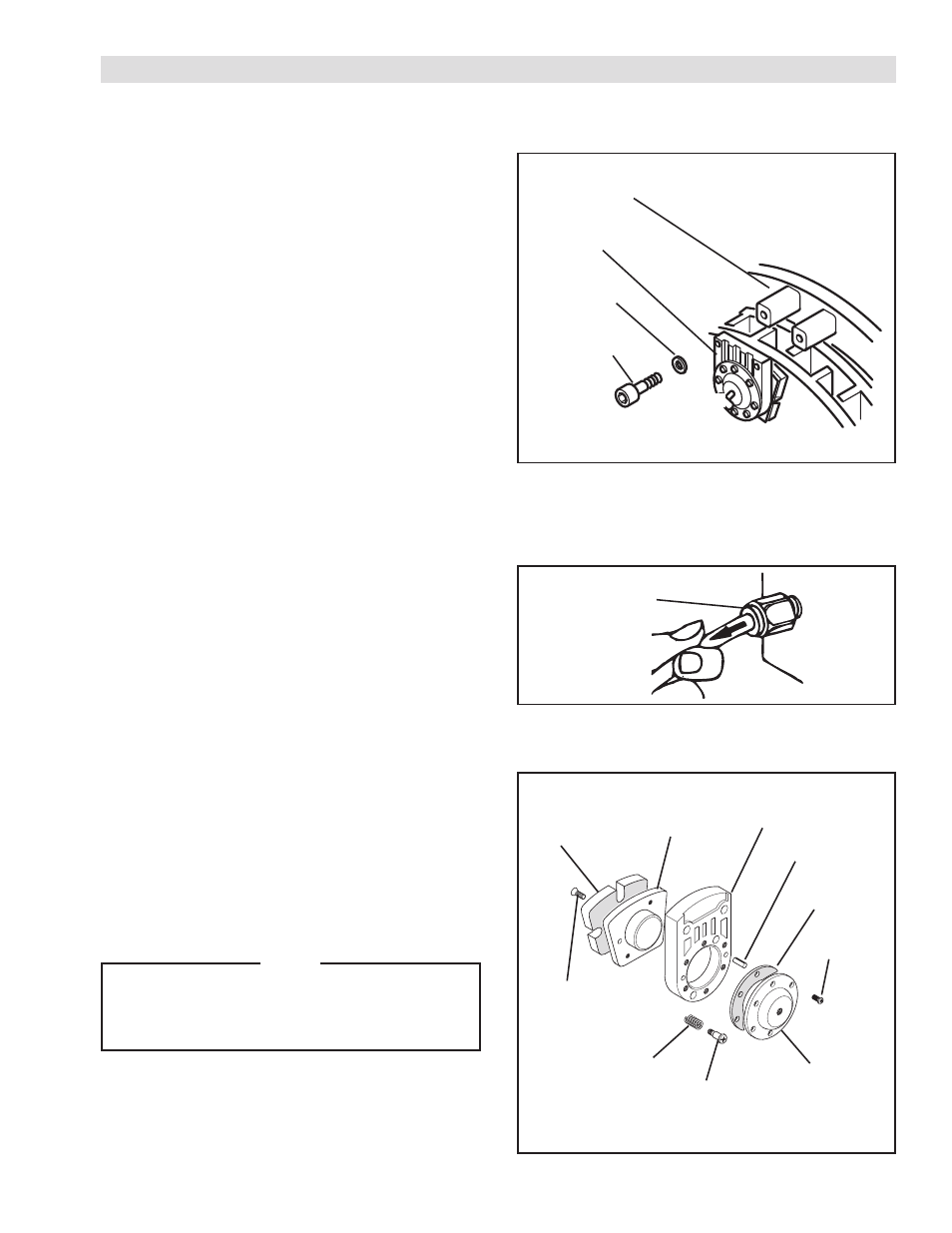
FRICTION FACINGS
REFER TO FIGURE 14.
1. Stop machine and shut off air supply to the TCB.
2. Remove Cap Screws (Item 18) and Lock Washers.).
3. Remove Caliper Assembly from Housing (Item 8).
4. Remove Machine Screw (Item 10) securing friction
facing to caliper and remove Facing from caliper.
5. Install new Friction Facing. Tighten screw to 18-19
in-lbs [2.0-2.1 Nm].
6. Place Caliper Assembly in position and replace Lock
Washers and Cap Screws.
7. Tighten Cap Screws (Item 18) to 27 ft-lbs [36.4 Nm].
AIR LINE
REFER TO FIGURE 15.
1. To disconnect air line, push in on collar of fitting, then
pull air line out of fitting.
2. To install new air line, push air line into fitting until it
stops.
Cap Screw
(Item 18)
Lock Washer
(Item 19)
Caliper
Assembly
Housing
(Item 8)
Release
Button
Spring Pin
(Item 21)
Diaphragm
(Item 14)
Shoulder Screw
(Item 40)
Friction
Facing
Piston
(Item 12)
Cylinder
(Item 11)
Cover
(Item 13)
Cap Screw
(Item 20)
Compression Spring
(Item 41)
Machine Screw
(Item 10)
FIGURE 14
FIGURE 15
FIGURE 16
DIAPHRAGM
REFER TO FIGURE 16.
1. Disconnect air line.
2. Remove Cap Screws (Item 18) and Lock Washers.
3. Remove Caliper Assembly from Housing (Item 8).
4. Remove six Cap Screws (Item 20) and Cover (Item
13) from Cylinder (Item 11).
5. Remove Diaphragm (Item 14).
NOTE
Internal Compression Springs may also be
removed at this time. These springs are optional;
the low air pressure setting is more sensitive
without the springs.
6. Replace the Diaphragm and reassemble the caliper.
7. Tighten the Shoulder Screw (Item 40) to 22 ft-lbs
[29.6 Nm] and the Cap Screw (Item 20) to 5.5 ft-lbs
[7.45 Nm] torque.