Nexen AE120 912674 User Manual
Page 9
9
FORM NO. L-20230-E-1107
OPERATION
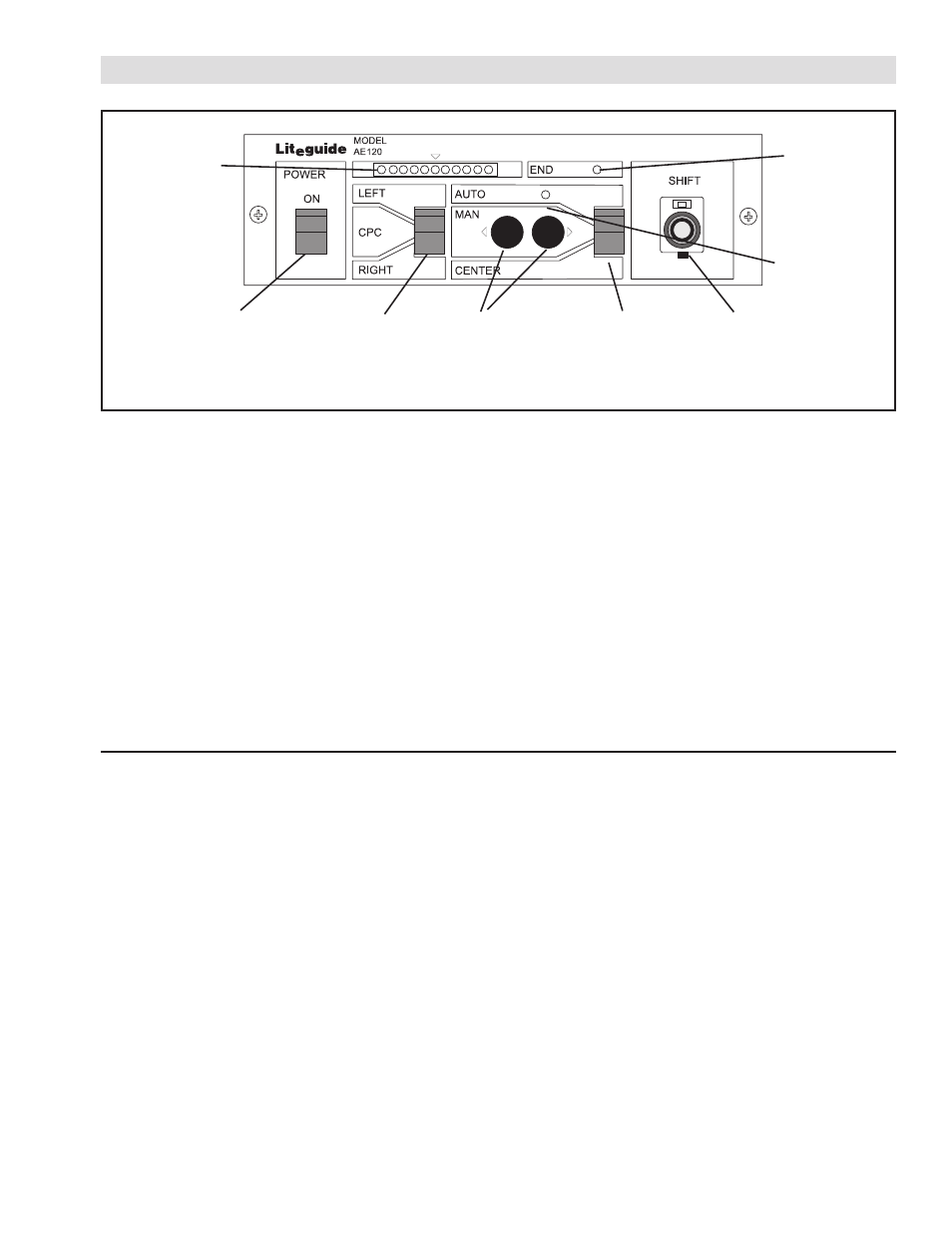
FIGURE 9
EPC
1. Set Mode Switch to CENTER (See Figure 9).
2. Set Fine Adjustment Control to 5.0 (mid-travel) (See
Figure 9).
3. Thread the web into the machine.
4. Align the web edge with the process.
5. Set the Sensor Selector Switch to LEFT or RIGHT
as appropriate (See Figure 9).
6. Move the sensor to the edge of the web until the
center green light in the Error Indicator array glows
(See Figure 9).
End of
Travel
LED
Auto
Indicator
Fine
Adjustment
Control
Manual
Push
Buttons
Mode
Switch
Sensor
Select
Switch
Power
Switch
Error
Indicator
CPC
1. Set the Mode Switch to CENTER (See Figure 9).
2. Set the Fine Adjustment Control to 5.0 (mid-travel)
(See Figure 9).
3. Thread the web into the machine.
4. Align the centerline of the web with the centerline of
the machine.
5. Set the Sensor Selector Switch to LEFT (See
Figure 9).
6. Move the left sensor to the web edge until the
center green light in the indicator array glows (See
Figure 9).
7. Set the Sensor Selector Switch to RIGHT (See
Figure 9).
7. Set the Mode Switch to
AUTO (See Figure 9).
8. Start the machine. The web should stay in the
center of the sensor and the green light should
remain on.
9. If the web is slightly misaligned with the process, it
can be moved with the Fine Adjustment Control
(plus or minus 0.20 In. [5 mm]) (See Figure 9).
10. Larger adjustments can be made with the sensor
mounting bracket (refer to the maintenance and
installation instructions provided with the sensor).
8. Move the right sensor to the edge of the web until
the center green light of the Error Indicator array
glows (See Figure 9).
9. Set the Sensor Selector Switch to
CPC (See
Figure 9).
10. Set the Mode Switch to AUTO (See Figure 9).
11. Start the machine. The web should stay centered
between the sensors and the green light should
remain on.
12. If the web is slightly misaligned with the center of
the machine, it can be moved with the Fine
Adjustment Control on the control panel (plus or
minus 0.20 In. [5 mm]) (See Figure 9).
13. For greater misalignment errors, repeat Steps 4-12.