Nexen AE120 912674 User Manual
Page 6
FORM NO. L-20230-E-1107
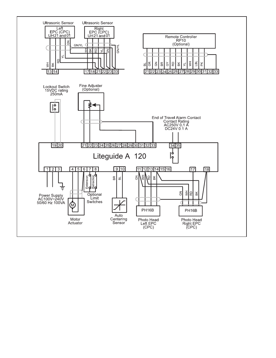
3. Using cables provided with the sensors, make the
connections for either left hand or right hand EPC, or
CPC (See Figure 6).
4. Connect AC Power in the range of 100 to 240VAC
to Terminals and 2. Connect Terminal to ground
(See Figure 6).
5. Connect motor output lead to Terminals and .
Connect cable shield to Terminal (See Figure 6).
6. Connect optional Travel Limit Switches to Terminals
, 7, and 8 (See Figure 6).
NOTE: If Limit Switches are not used, short all three
terminals together.
7. Connect Automatic Centering Sensor (Product No.
912696) to Terminals 9 and 0 (See Figure 6).
8. Connect the optional Lock Out Switch to Terminals
9 and 20 (See Figure 6).
NOTE: The Lock Out Switch is a customer supplied
switch rated at 15VDC, 250mA, N.O.,
momentary contact.
9. If used, connect optional RP10 Remote Controller
(Product No. 912695) to Terminals 2-2 (See
Figure 6).
10. If used, connect a customer supplied Remote Fine
Adjustment Pot, rated 10K ohm, to Terminals 2, 22,
0, and (See Figure 6).
FIGURE
E