Calibration and adjustment – Nexen AE120 912674 User Manual
Page 7
7
FORM NO. L-20230-E-1107
CALIBRATION AND ADJUSTMENT
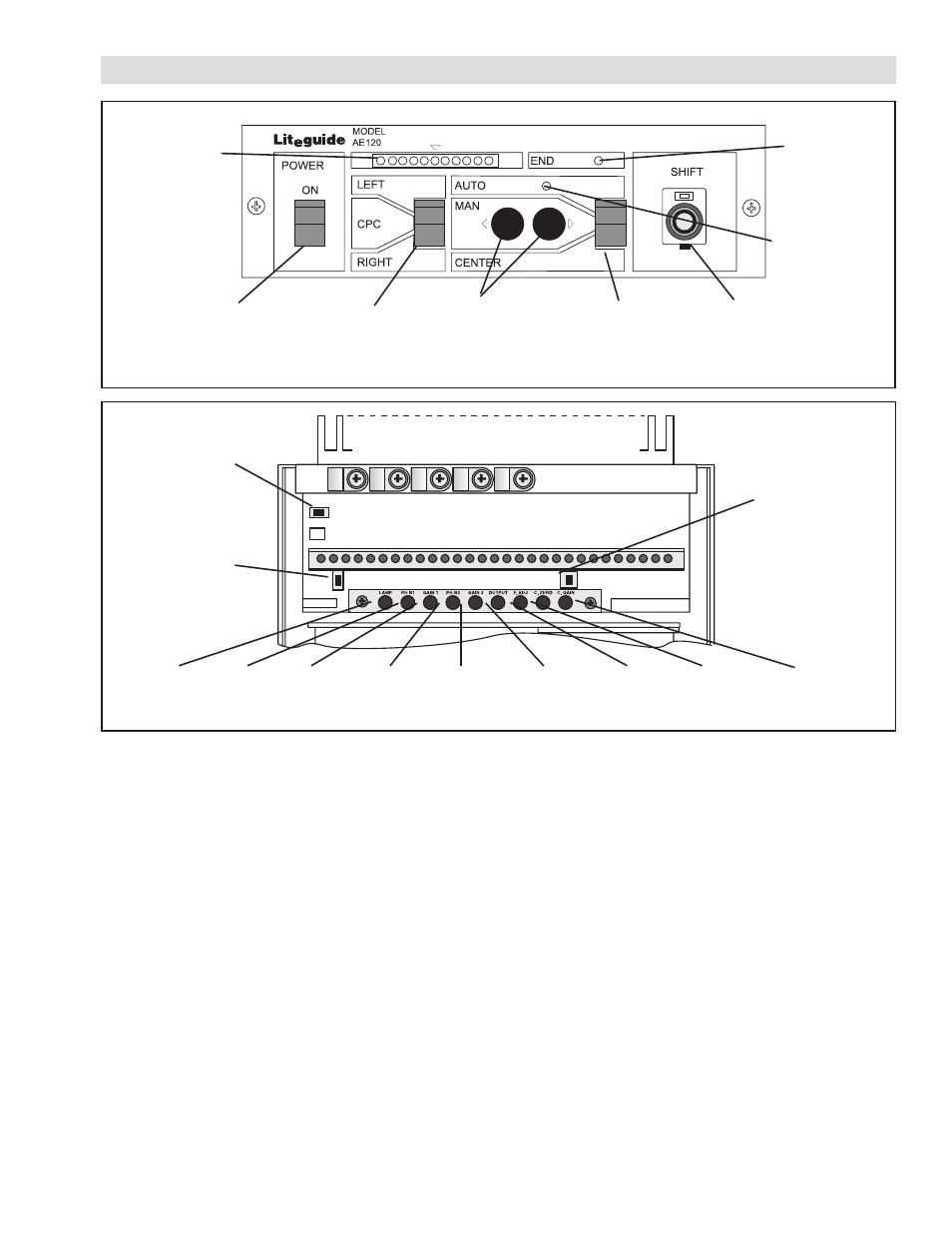
FIGURE 7
End of
Travel
LED
Auto
Indicator
Fine
Adjustment
Control
Manual
Push
Buttons
Mode
Switch
Sensor
Select
Switch
Power
Switch
FIGURE 8
LAMP
PHB1
GAIN 1
PHB2
GAIN 2
OUTPUT
F. ADJ
C. ZERO
C. GAIN
NOR/REV
Switch for
MANUAL
Operation
NOR/REV
Switch for
CENTER
Operation
NOR/REV
Switch for
AUTO
Operation
Error
Indicator
SENSOR CALIBRATION
EPC Calibration
1. Set Fine Adj. Pot on the front panel to 5.0 (mid-travel)
(See Figure 7).
2. Using the Sensor Select Switch located on the front
panel, select either the RIGHT or LEFT Sensor (See
Figure 7).
3. Insert a piece of material until it completely covers the
sensing area of the sensor; then, remove the material.
The Error Indicator array will light up to show
maximum and minimum insertion with up to five red
lights on either side of the center green light (See
Figure 7).
NOTE: Use opaque material with PH16 and PH46
and soundproof material with the UH21 and
UH01.
4. Rotate the Photo Head Balance Pot (PHB for the
left sensor and
PH2B for the right sensor) until the
insertion and removal of material lights up an equal
number of red lights on either side of the green light
on the Error Indicator array (See Figures 7 and 8).
5. Rotate GAIN for the left sensor and GAIN 2 for the
right sensor until the insertion of material illuminates
five red lights in either direction (See Figures 7 and 8).
CPC Calibration
1. Perform EPC Calibration separately for each sensor.
2. Set the Sensor Selector Switch to the CPC position
(See Figure 7).