Installation, Guard installation – Nexen XTB 10-18 Dual Disc Caliper 835500 User Manual
Page 7
7
FORM NO. L-20183-L-1209
FrICTION FACING
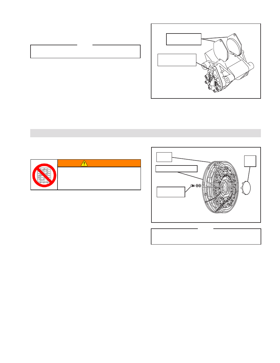
refer to Figure 8.
NOTE
STD Friction Facings have a red stripe and LOCO Friction
Facings have a green stripe.
1. Pull out the Shoe Retaining Pin.
2. Slide the Friction Facings into the space between the Caliper
and Rotor until the cutout on each Friction Facing is against
the lug on the Caliper.
3. Secure the Friction Facings by sliding the Shoe Retaining
Pin back into the Caliper and through the holes in the Friction
Facings.
4. Repeat Steps 1-3 to install all Friction Facings.
FIGurE 8
Slide Friction
Facings in
Pull out Shoe
retaining Pin
INSTALLATION
(continued)
refer to Figure 9.
1. Slide the Ring Guard over the XTB Caliper Brake
Assembly by aligning the Ring Guard attachment hook
ends with the notches in the XTB Mounting Ring; then,
turn the Ring Guard to the closest attachment hole.
2. Secure the Ring Guard to the Mounting Ring of the
XTB Caliper Brake Assembly using the eight Socket
Head Cap Screws. Tighten to 50 in lbs [5,6 Nm].
3. If the Ring Guard is shipped with an End Cap, slide
the End Cap onto the Ring Guard; then, secure it in
place by bending the tabs on the End Cap around the
Ring Guard.
ring
Guard
XTB Mounting ring
Socket Head
Cap Screws
FIGurE 9
End
Cap
WARNING
Ensure proper guarding of the product is used.
Nexen recommends the machine builder
design guarding in compliance with OSHA 29
CFR 1910 “Occupational Safety and Health
Hazards”.
GuArD INSTALLATION
NOTE
Ring Guard product numbers are located in the
Replacement Parts section.
- XTB 22-30 Dual Disc Caliper 835570 XTB 22-30 Single Disc Caliper 835560 XTB10 835401 XTB10 835402 XTB10 835403 XTB10 835404 XTB10 835405 XTB10 835406 XTB-10 835508 XTB-10 835619 XTB-14 835644 XTB-14 835616 XTB-14 835421 XTB-14 835422 XTB-14 835427 XTB-14 835507 XTB-14 835423 XTB-14 835424 XTB-14 835632 XTB-14 835633 XTB-14 835425 XTB-14 835426 XTB-14 835639 XTB-14 835583 XTB-12 835411 XTB-12 835412 XTB-12 835413 XTB-12 835414 XTB-12 835415 XTB-12 835416 XTB-12 835596 XTB-12 835597 XTB-12 835557 XTB-12 835437 XTB-18 835645 XTB-18 835516 XTB-18 835517 XTB-18 835605 XTB-18 835606 XTB-18 835680 XTB-18 835681 XTB-18 835431 XTB-18 835432 XTB-18 835433 XTB-18 835434 XTB-18 835696 XTB-18 835435 XTB-18 835436 XTB-18 835575 XTB-18 835620 XTB-18 835499 XTB-18 835491 XTB-18 835492 XTB-18 835493 XTB-18 835494 XTB-18 835495 XTB-18 835496 XTB-22 835697 XTB-22 835540 XTB-22 835541 XTB-22 835542 XTB-22 835543 XTB-22 835544 XTB-22 835545 XTB-22 835698 XTB-22 835649 XTB-22 835550 XTB-22 835551 XTB-22 835552 XTB-22 835553 XTB-22 835554 XTB-22 835555 XTBA10 835677 XTBA10 835650 XTBA10 835651 XTBA10 835652 XTBA10 835653 XTBA10 835654 XTBA10 835655 XTBA14 835689 XTBA14 835687 XTBA14 835688 XTBA14 835683 XTBA14 835662 XTBA14 835663 XTBA14 835678 XTBA14 835679 XTBA14 835691 XTBA14 835664 XTBA14 835665 XTBA14 835666 XTBA14 835667 XTBA12 835656 XTBA12 835657 XTBA12 835695 XTBA12 835658 XTBA12 835659 XTBA12 835660 XTBA12 835661 XTBA18 835684 XTBA18 835682 XTBA18 835668 XTBA18 835669 XTBA18 835670 XTBA18 835671 XTBA18 835676 XTBA18 835672 XTBA18 835673 XTBA18 835690 XTB Guard 835446 XTB Guard 835447 XTB Guard 835448 XTB Guard 835445 XTB Guard 835444 XTB Guard 835449