Nexen XTB 10-18 Dual Disc Caliper 835500 User Manual
Page 6
FORM NO. L-20183-L-1209
6
CALIPEr
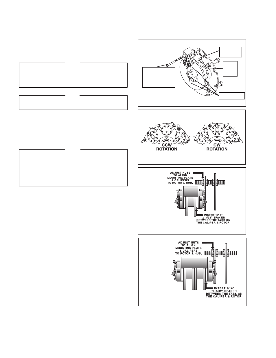
refer to Figures 4 - 7.
1. Slide one Caliper Assembly over the Rotor and Hub.
NOTE
For best thermal dissipation, align the Caliper
Assembly as shown in relation to the direction of
rotor rotation. Direction of rotor rotation is stamped
in the rotor.
NOTE
remove and discard the two Hex. Nuts used to hold
the Caliper Assembly together during shipping.
2. Using Socket Head Cap Screws, Flat Washers, and
Lock Washers, secure the Caliper Assembly to the
Mounting Ring.
3. Tighten the Socket Head Cap Screws.
NOTE
On Models XTB-10, 12, 14, and 18, tighten the
Socket Head Cap Screws to 45 Ft. Lbs. [61 N•m]
torque.
On Model XTB-22, tighten the Socket Head Cap
Screws to 110 Ft. Lbs. [149 N•m] torque.
4. Repeat Steps 1-3 to install the remaining Caliper
Assemblies.
5. Slide the Rotor and Hub on the machine shaft until it
is snug against the Caliper Assemblies.
6. Tighten Set Screws.
7. Align the Mounting Ring and Calipers to the Rotor(s)
and Hub Assembly by adjusting the Nuts until a 1/16-
3/32'' spacer can be inserted between the tabs on
the Caliper and Rotor (See Figure 6 for Single Rotor
and Figure 7 for Dual Rotor alignment procedures).
8. Tighten the Hex. Head Jam Nuts to 131 Ft. Lbs. [178
N•m] torque.
FIGurE 7
DuAL rOTOr XTB ALIGNMENT
FIGurE 6
SINGLE rOTOr XTB ALIGNMENT
FIGurE 5
Socket Head
Cap Screws,
Washers, and
Lock Washers
Caliper
Assembly
rotor
and
Hub
FIGurE 4
Set Screws
INSTALLATION
(continued)
- XTB 22-30 Dual Disc Caliper 835570 XTB 22-30 Single Disc Caliper 835560 XTB10 835401 XTB10 835402 XTB10 835403 XTB10 835404 XTB10 835405 XTB10 835406 XTB-10 835508 XTB-10 835619 XTB-14 835644 XTB-14 835616 XTB-14 835421 XTB-14 835422 XTB-14 835427 XTB-14 835507 XTB-14 835423 XTB-14 835424 XTB-14 835632 XTB-14 835633 XTB-14 835425 XTB-14 835426 XTB-14 835639 XTB-14 835583 XTB-12 835411 XTB-12 835412 XTB-12 835413 XTB-12 835414 XTB-12 835415 XTB-12 835416 XTB-12 835596 XTB-12 835597 XTB-12 835557 XTB-12 835437 XTB-18 835645 XTB-18 835516 XTB-18 835517 XTB-18 835605 XTB-18 835606 XTB-18 835680 XTB-18 835681 XTB-18 835431 XTB-18 835432 XTB-18 835433 XTB-18 835434 XTB-18 835696 XTB-18 835435 XTB-18 835436 XTB-18 835575 XTB-18 835620 XTB-18 835499 XTB-18 835491 XTB-18 835492 XTB-18 835493 XTB-18 835494 XTB-18 835495 XTB-18 835496 XTB-22 835697 XTB-22 835540 XTB-22 835541 XTB-22 835542 XTB-22 835543 XTB-22 835544 XTB-22 835545 XTB-22 835698 XTB-22 835649 XTB-22 835550 XTB-22 835551 XTB-22 835552 XTB-22 835553 XTB-22 835554 XTB-22 835555 XTBA10 835677 XTBA10 835650 XTBA10 835651 XTBA10 835652 XTBA10 835653 XTBA10 835654 XTBA10 835655 XTBA14 835689 XTBA14 835687 XTBA14 835688 XTBA14 835683 XTBA14 835662 XTBA14 835663 XTBA14 835678 XTBA14 835679 XTBA14 835691 XTBA14 835664 XTBA14 835665 XTBA14 835666 XTBA14 835667 XTBA12 835656 XTBA12 835657 XTBA12 835695 XTBA12 835658 XTBA12 835659 XTBA12 835660 XTBA12 835661 XTBA18 835684 XTBA18 835682 XTBA18 835668 XTBA18 835669 XTBA18 835670 XTBA18 835671 XTBA18 835676 XTBA18 835672 XTBA18 835673 XTBA18 835690 XTB Guard 835446 XTB Guard 835447 XTB Guard 835448 XTB Guard 835445 XTB Guard 835444 XTB Guard 835449