Nexen XTB 10-18 Dual Disc Caliper 835500 User Manual
Page 12
FORM NO. L-20183-L-1209
12
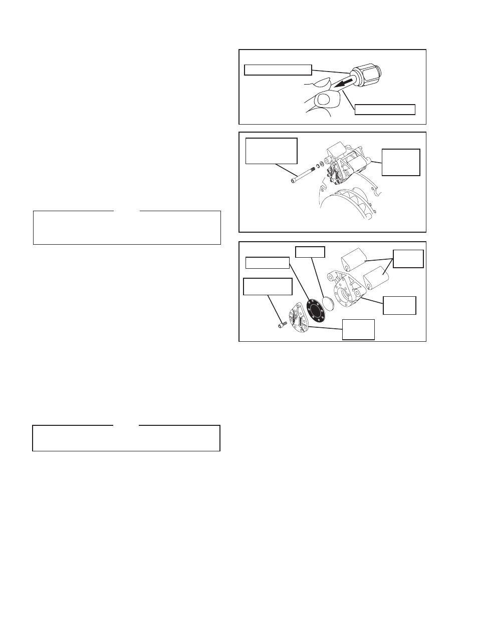
FIGurE 16
Push the collar in
Pull air line out
Caliper
Cap
Caliper
Housing
FIGurE 18
Socket Head
Cap Screws
Diaphragm
Piston
Caliper
Spacers
remove
Caliper
Assembly
FIGurE 17
remove
Socket Head
Cap Screws
DIAPHrAGM
refer to Figures 16 - 18.
1. Stop the machine, shut off the air supply, and ensure
safety lockouts are installed to prevent accidental
machine start-up.
2. Remove the Ring Guard.
3. Remove the Friction Facings (See PArTS
rEPLACEMENT—FRICTION FACINGS).
4. Disconnect the air lines from the Caliper by pushing
in on collar of the fitting; then, pull the air line out of
the fitting.
NOTE
Mark the orientation of the Caliper Spacers (Item 9)
in relation to the Caliper Housing (Item 1) to ensure
correct orientation during reassembly.
5. Remove the Caliper Assembly from the Mounting
Ring.
a. Remove the Socket Head Cap Screw securing
the Caliper to the Mounting Ring.
b. Slide the Caliper free of the Rotor and Mounting
Ring.
6. Remove the Socket Head Cap Screws securing the
Caliper Cap to the Caliper Housing and remove the
Caliper Cap.
7. Remove the old Diaphragm and Piston.
8. Remove the old Diaphragm from the Piston; then, slide
the Piston back into the Caliper Housing.
NOTE
The holes in the Diaphragm must be aligned with
the holes in the Caliper Housing.
9. Place a new Diaphragm (dull side towards Caliper
Housing) over the Piston and Caliper Housing.
10. Place the Caliper Cap on the Caliper Assembly.
PArTS rEPLACEMENT (continued)
11. Install and tighten the Socket Head Cap Screws to
1.75 Ft. Lbs. [2.4 N•m] torque.
12. Install the Caliper to the Mounting Ring (See
INSTALLATION—CALIPER).
13. Install the Friction Facings (See INSTALLATION—
FRICTION FACINGS).
14. Connect the air lines.
15. Reinst all the Ring Guard (See G uAr D
INSTALLATION).
- XTB 22-30 Dual Disc Caliper 835570 XTB 22-30 Single Disc Caliper 835560 XTB10 835401 XTB10 835402 XTB10 835403 XTB10 835404 XTB10 835405 XTB10 835406 XTB-10 835508 XTB-10 835619 XTB-14 835644 XTB-14 835616 XTB-14 835421 XTB-14 835422 XTB-14 835427 XTB-14 835507 XTB-14 835423 XTB-14 835424 XTB-14 835632 XTB-14 835633 XTB-14 835425 XTB-14 835426 XTB-14 835639 XTB-14 835583 XTB-12 835411 XTB-12 835412 XTB-12 835413 XTB-12 835414 XTB-12 835415 XTB-12 835416 XTB-12 835596 XTB-12 835597 XTB-12 835557 XTB-12 835437 XTB-18 835645 XTB-18 835516 XTB-18 835517 XTB-18 835605 XTB-18 835606 XTB-18 835680 XTB-18 835681 XTB-18 835431 XTB-18 835432 XTB-18 835433 XTB-18 835434 XTB-18 835696 XTB-18 835435 XTB-18 835436 XTB-18 835575 XTB-18 835620 XTB-18 835499 XTB-18 835491 XTB-18 835492 XTB-18 835493 XTB-18 835494 XTB-18 835495 XTB-18 835496 XTB-22 835697 XTB-22 835540 XTB-22 835541 XTB-22 835542 XTB-22 835543 XTB-22 835544 XTB-22 835545 XTB-22 835698 XTB-22 835649 XTB-22 835550 XTB-22 835551 XTB-22 835552 XTB-22 835553 XTB-22 835554 XTB-22 835555 XTBA10 835677 XTBA10 835650 XTBA10 835651 XTBA10 835652 XTBA10 835653 XTBA10 835654 XTBA10 835655 XTBA14 835689 XTBA14 835687 XTBA14 835688 XTBA14 835683 XTBA14 835662 XTBA14 835663 XTBA14 835678 XTBA14 835679 XTBA14 835691 XTBA14 835664 XTBA14 835665 XTBA14 835666 XTBA14 835667 XTBA12 835656 XTBA12 835657 XTBA12 835695 XTBA12 835658 XTBA12 835659 XTBA12 835660 XTBA12 835661 XTBA18 835684 XTBA18 835682 XTBA18 835668 XTBA18 835669 XTBA18 835670 XTBA18 835671 XTBA18 835676 XTBA18 835672 XTBA18 835673 XTBA18 835690 XTB Guard 835446 XTB Guard 835447 XTB Guard 835448 XTB Guard 835445 XTB Guard 835444 XTB Guard 835449